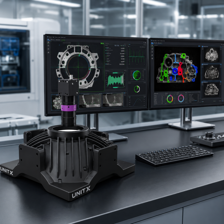
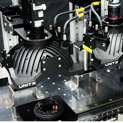
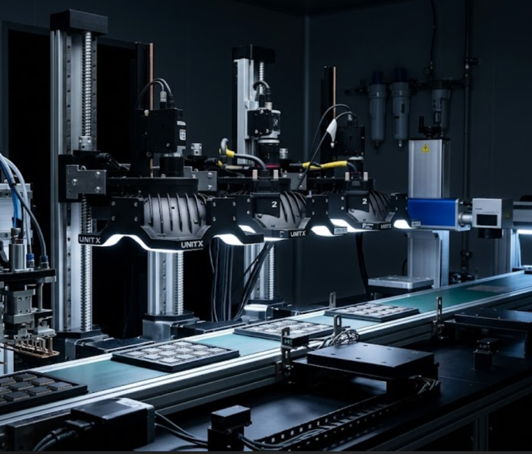
Most machine vision procurement processes go wrong at the same point: engineers evaluate vendor demos before creating a written specification. Vendor demos are designed to showcase systems performing well under ideal conditions. Software-defined imaging systems generate particularly convincing demos because multi-channel lighting produces visibly better images than a single-fixture setup.
The real engineering question, however, is whether those better images actually translate into improved defect recall for your specific parts and defect mix. That question is answered during the specification and validation stage, not during the demo.
The global machine vision market is projected to grow from $15.83 billion in 2025 to $23.63 billion by 2030, with a proliferating vendor landscape that makes structured selection frameworks more valuable than ever.
This guide provides the four-step selection framework we have developed across more than 100 production line deployments. It is written for quality engineers and process engineers who oversee inspection specifications but may have limited visibility into AI vendor claims, and who need to close a vendor selection decision within a quarter.
Key Takeaways
- Write the inspection specification before watching a single demo. A specification that defines minimum defect size, required recall rate, line speed, and data integration requirements turns a vendor demo into a pass or fail test.
- Sample efficiency is the most important claim to test live. Any vendor claiming their system can train from 5 images should demonstrate it in front of you using your defect samples, not on a prepared benchmark dataset.
- Edge inference latency and PLC integration are make-or-break technical requirements. Systems that require cloud inference for production decisions, or cannot reliably trigger reject mechanisms within the part dwell time, will not function effectively on high-speed lines.
- Total cost of ownership includes integration labor and model retraining time, not just hardware costs. High program setup time becomes a recurring cost on high-mix production lines.
Step 1: Define Inspection Scope Before Contacting Vendors
The inspection specification is the document against which every vendor demo should be evaluated. It takes one day to write and can save weeks of vendor management time. The specification should answer five key questions.
Question 1: What are the defect types and minimum detectable sizes?
List every defect category that has caused production escapes or customer complaints in the past 12 months. For each category, document a physical example, the minimum size at which the defect becomes rejectable, and the surface condition (reflective, matte, textured, or transparent) in which it appears.
Question 2: What are the required False Acceptance Rate and False Rejection Rate?
These are the two core performance metrics for any inspection system. We target False Acceptance (FA) = 0% and False Rejection (FR) ≤ 1% in our deployments. Document your requirements explicitly. A system that achieves 95% recall is not acceptable if 5% of defects still reach your customer.
Question 3: What is the line speed and available inspection window?
The minimum imaging resolution and maximum cycle time follow directly from these two numbers. If your line runs at 400 mm/s and the part is 100 mm long, the system has 250 ms per part. After accounting for PLC triggers latency and reject mechanism response time, the AI inference budget is typically under 50 ms.
Question 4: What integration points are mandatory?
Document which PLC protocol your line uses, which MES receives inspection data, and whether data must be logged to a quality management system for regulatory traceability. Research on machine vision and PLC integration for Industry 4.0 confirms that integration failure, not AI accuracy, is the most common reason production inspection deployments are delayed or abandoned.
Question 5: What is the defect sample inventory?
Count the physical defect samples available for model training. If the answer is fewer than 10 per category, the system must support sample-efficient AI training or synthetic data augmentation. Systems that require 500 or more samples per category cannot be deployed on lines where defects are intentionally rare by design.
Step 2: Write The Imaging Specification
The imaging specification translates the inspection scope into measurable hardware requirements. The three key parameters are spatial resolution (pixels per millimeter at the inspection distance), field of view (the area covered in a single capture), and imaging speed (whether fly capture at full line speed is required or whether stop-and-shoot staging is acceptable).
Spatial resolution is derived from the minimum detectable defect size. To reliably detect a defect, the pixel dimension at the part surface must be 3x to 5x smaller than the minimum defect size. For a 0.1 mm minimum defect, the system needs at least 30 µm per pixel, requiring a camera with sufficient resolution to cover the field of view at that pixel density.
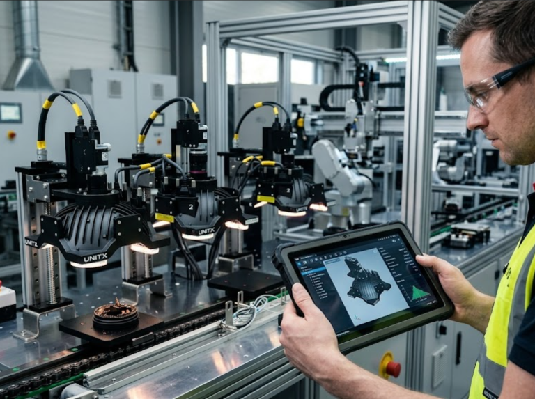
Software-defined lighting (SDL) requirements depend on defect geometry. Surface scratches and abrasions are best revealed under raking dark-field illumination. Dimensional defects respond well to backlighting. Contamination and staining respond to coaxial diffuse illumination. For products with multiple defect types spanning different surface conditions, SDL with independent multi-channel control is necessary. A system with only brightfield or only ring illumination will miss defect categories that require different lighting geometries. Research published in the International Journal demonstrates that hybrid imaging approaches combining multiple illumination modes consistently outperform single-mode configurations for complex surface defect applications.
Fly capture capability is binary: the system either supports it at your line speed or it does not. At 400 mm/s or above, stop-and-shoot inspection requires mechanical staging that adds cost, complexity, and potential production bottlenecks. Ask every vendor for their maximum fly capture speed in meters per second under the specific optical configuration you require, not under ideal conditions.
Step 3: Benchmark Sample Efficiency with Your Actual Defect Samples
Sample efficiency is the most frequently overstated claim in AI inspection procurement. Every vendor can demonstrate good results on a prepared benchmark dataset with hundreds of carefully labeled samples. The test that matters is whether the system can train a production-grade model from 5 to 10 of your actual defect samples, in your presence, in under an hour.
We train effective CorteX models using as few as 5 labeled defect images per category (UnitX data on file). For categories where even 5 samples are difficult to collect, FleX-Gen generates synthetic training data from 3 real samples. The 30-minute training cycle means a new part program can be configured and validated before the end of a shift.
Before signing a purchase order with any vendor, require a live demonstration using your defect samples, not theirs. Benchmarking research published in the Journal of Intelligent Manufacturing confirms that model performance on vendor-provided demonstration datasets does not reliably predict performance on site-specific production defects, making live evaluation with real production samples the only credible test.
During the live test, document:
- The number of training images used
- The training time in minutes
- The recall rate on a hold-out test set of known defect samples
- The false rejection rate on a set of known-good parts
These four numbers are the key production-readiness indicators that determine whether the system is viable on your line.
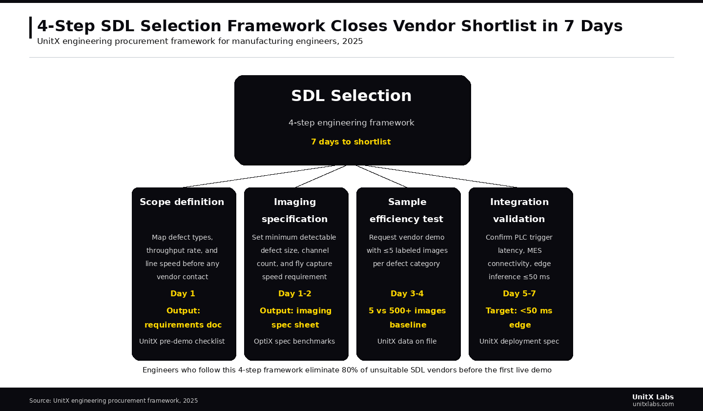
Engineers who follow this 4-step framework eliminate 80% of unsuitable SDL vendors before the first live demo
Step 4: Validate Integration Depth Before Purchase Commitment
Integration failures are the most expensive machine vision procurement mistakes because they typically surface after the purchase order is signed and the hardware is installed. The validation checklist for integration depth has three categories.
PLC and reject mechanism integration
The vision system must send a pass-or-fail signal to the PLC within the part dwell time after image capture. For most discrete-part applications, this window ranges from 50 ms to 150 ms. Ask the vendor for their measured latency from image capture trigger to PLC output signal using your specific hardware configuration. Require this to be documented in writing.
MES connectivity
Confirm that the inspection system can write defect records, inspection images, and timestamps to your MES using the protocol your MES accepts (OPC-UA, REST API, Modbus, or a vendor-specific connector). Ask for a documented integration pattern for your specific MES platform. Infosys’s analysis of semiconductor yield improvement identifies end-to-end MES connectivity as the critical enabler of closed-loop quality control that delivers sustained yield gains beyond the initial inspection deployment.
Edge vs. cloud architecture
Confirm that AI inference runs on edge hardware at the inspection station without dependency on cloud connectivity. Cloud-dependent inference introduces unacceptable latency for reject mechanism triggering and creates a production-stop risk when network connectivity becomes intermittent.
We deploy CorteX as an edge-first, with cloud connectivity used only for model management and aggregate analytics, never for production inference decisions. Autodesk’s manufacturing quality analysis identifies system reliability and integration robustness as primary factors in determining whether COPQ reduction programs deliver sustained financial returns rather than one-time improvements.
A Checklist to Evaluating Software-Defined Imaging Systems
Before issuing an RFP or entering vendor negotiations, confirm that the following items are documented in your inspection specification. We use this checklist in every new manufacturing solutions engagement.
- Defect types and minimum detectable sizes documented with physical examples
- Required FA = 0% and FR ≤1% (or facility-specific equivalents) written as acceptance criteria
- Line speed and maximum inspection cycle time calculated
- PLC protocol and reject mechanism dwell time documented
- MES integration protocol and data schema defined
- Defect sample inventory counted per category
- Minimum SDL channel count derived from defect and surface analysis
- Fly capture speed requirement set (or stop-and-shoot staging budget confirmed)
- Edge inference latency requirement of ≤ 50 ms documented
- Live vendor demo test protocol defined using your samples, not vendor samples
Combining our experience across more than 100 production lines with machine vision lighting market data showing 31% growth in programmable lighting adoption from 2022 to 2025, a practical conclusion emerges for manufacturing engineers evaluating SDL systems: the market has moved faster than procurement processes.
Many plants are still evaluating SDL systems using RFPs designed for fixed-configuration machine vision. These RFPs lack the specifications needed to differentiate between a 4-channel system and a 32-channel system, or between a platform with 30-minute training and one that requires weeks of setup.
Updating the procurement specification to include channel count, training data requirements, and latency benchmarks is the single highest-leverage action an engineering team can take before entering the vendor selection process. IEEE’s manufacturing technology review confirms that structured procurement and deployment practices, not technology availability alone, determine whether AI inspection systems deliver measurable quality outcomes.
Frequently Asked Questions
How many lighting channels does a software-defined imaging system actually need for my application?
Start with defect variety. For a single surface defect class on a uniform material, a 4-channel system may be sufficient. For three or more defect classes across materials with varying surface conditions, 16 to 32 channels provide meaningfully better coverage.
The limiting factor is rarely cost. The real cost driver is the engineering time required to configure and validate multi-channel lighting profiles on a system with fewer channels. We configure OptiX’s 32-channel SDL for most applications in under 30 minutes (UnitX data on file) because the broader channel eliminates the iterative calibration cycles required by simpler systems.
What is the correct way to compare SDL systems from different vendors?
Compare four documented metrics, not demo quality:
- Maximum fly capture speed at the specific resolution and lighting configuration required for your application
- Maximum number of independent SDL channels
- Model training data requirements per defect category, tested using your samples
- Measured PLC output latency
All four metrics should be provided in writing. Avoid comparing systems when a vendor cannot provide all four as documented specifications rather than verbal estimates. Manufacturing technology research consistently identifies specification gaps as the root cause of mismatched expectations between procurement teams and production performance.
How long does a software-defined imaging deployment typically take?
On the UnitX AI visual inspection platform, deploying a new production line, from assessment through Site Acceptance Testing (SAT), typically takes 7 days.
This is substantially faster than legacy machine vision installations, which often require 4 to 8 weeks for lighting calibration, rule-based threshold programming, and validation. The faster deployment timeline comes from sample-efficient AI training and preconfigured SDL lighting profiles that adapt to new parts instead of requiring manual recalibration.
The MES integration step is typically the most variable. Sites with standardized OPC-UA MES interfaces can complete integration within days, while sites using custom or legacy MES platforms may require additional engineering time.