Camera resolution, pixel counts, and lens specifications often dominate the conversation when quality engineers evaluate machine vision systems — but lighting is what ultimately determines whether a defect appears in the image at all. A 50 MP camera paired with the wrong illumination geometry will systematically miss the micro-scratches, edge burrs, or coating defects that matter most to your quality process.
Lighting selection is not a one-time setup task performed during installation. In traditional fixed-lighting systems, every new part geometry, material, or defect type requires lighting reconfiguration — a process that can take days and represents a hidden cost that accumulates over a system’s production lifetime.
This guide covers the six core machine vision lighting techniques used in manufacturing inspection, the decision logic for selecting among them, and how software-defined illumination is changing the equation entirely.
Key Takeaways
- Lighting geometry determines contrast — cameras detect brightness differences, not defects. The right illumination geometry turns an invisible defect into a high-contrast feature that an AI model can classify.
- Darkfield is non-negotiable for detecting micro-scratches on reflective metal surfaces. No amount of camera resolution can compensate for a brightfield setup in these applications.
- Backlighting is the highest-contrast technique for dimensional measurement and presence/absence detection, but it cannot inspect surface detail on opaque parts.
- Software-defined lighting eliminates the tradeoff between illumination modes by cycling through 50 lighting configurations per second and compositing the results — a single system can handle any defect type or surface material without reconfiguration.
- Poor lighting inflates training data requirements. An AI model trained on images with inconsistent illumination requires more labeled samples to achieve equivalent accuracy — correct lighting setup is the highest-leverage investment for reducing data collection time.
Why Lighting Is the Highest-Leverage Variable in Machine Vision
Cameras Detect Contrast, Not Defects
This distinction matters more than most engineers recognize when specifying a vision system. Every machine vision system — whether rule-based or AI-powered — analyzes pixel intensity patterns to distinguish “acceptable” from “defective.” The camera cannot infer information that was never present in the image.
A 0.03mm scratch on a polished aluminum surface may scatter less than 0.1% of incident light under brightfield illumination, rendering it invisible to any camera at any resolution. The same scratch, under low-angle darkfield illumination, scatters nearly 100% of incident light directly toward the sensor, appearing as a bright line against a dark background.
The defect did not become more detectable because the AI model improved — it became detectable because the illumination geometry changed how the physics of light interacted with the surface.
Lighting Variability Is an AI Training Cost
For AI-powered inspection systems, inconsistent lighting creates a compounding problem. When production lighting conditions vary — due to ambient light changes, LED aging, or part positioning variation — the AI model sees a wider distribution of image appearances for each defect type than necessary.
This forces the training process to use more labeled samples to cover the illumination variation rather than defect variation. According to Voxel51’s 2025 Visual AI in Manufacturing landscape report, data scarcity and robustness in harsh environments are the top unsolved challenges in factory AI deployment — both of which are directly exacerbated by inconsistent lighting.
Getting the lighting right before training models is the single most cost-effective investment a quality engineer can make to reduce time to deployment.
The 6 Core Machine Vision Lighting Techniques
1. Brightfield Illumination
Brightfield is the most widely deployed illumination mode: light is directed from the same side as the camera, and flat surfaces facing the light appear bright. Surface features: raised edges, embossed text, and material transitions, create contrast by reflecting light at angles outside the camera’s acceptance angle.
According to National Instruments’ practical machine vision lighting guide, brightfield is most effective for inspection tasks where features create natural contrast against a uniform background: print verification, barcode reading, label inspection, and surface markings on matte materials. Its primary limitation is performance on low-relief defects — a shallow scratch on a flat metal surface produces insufficient angular scatter to create contrast under direct brightfield illumination, making it invisible to the system.
2. Darkfield Illumination
Darkfield places the light source at a very low angle relative to the part surface — typically below 15 degrees. Under normal (specular) reflection, this low-angle light reflects away from the camera. However, surface discontinuities: scratches, burrs, particles, pinholes, scatter the light in multiple directions, including toward the camera.
The result is that defects appear bright against a dark background: the highest-contrast imaging scenario possible for surface defect detection. Per ProPhotonix’s illumination comparison guide, darkfield is particularly effective on reflective or mirrored surfaces where brightfield creates glare that obscures defects of interest. For polished metal components, semiconductor wafers, and battery tab welds, darkfield is frequently the only technique capable of resolving micro-scale defects at production line speeds.
3. Backlighting
Backlighting places the illumination source behind the part, with the camera looking through or around the object toward a bright background. Opaque parts appear as sharp silhouettes against a bright field, enabling highly accurate edge detection and dimensional measurement — such as verifying hole tolerances, connector pin presence, or seal integrity.
A comprehensive machine vision lighting guide from Roboflow notes that backlighting reliably handles both opaque and semi-transparent objects: opaque items produce sharp silhouette contrast for size and shape measurement, while translucent materials reveal internal defects or thickness variations. The limitation is that backlighting provides no information about the surface of an opaque part — it cannot detect scratches, contamination, or coating defects on the top face of a component. Surface inspection requires front-illumination techniques.
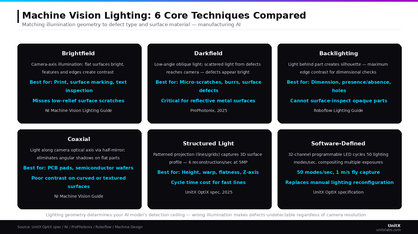
Lighting geometry determines your AI model’s detection ceiling — incorrect illumination makes defects undetectable regardless of camera resolution
4. Coaxial Illumination
Coaxial illumination directs light along the camera’s optical axis using a half-mirror or beamsplitter, so that illumination and imaging share the same path. Flat surfaces facing the camera reflect this light directly back toward the sensor, appearing uniformly bright. Any feature that is not perpendicular to the optical axis — edges, recesses, or curved sections — reflects light away from the sensor, appearing dark.
This technique is highly effective for flat, highly reflective surfaces: PCB pad inspection, semiconductor wafer surface uniformity, and flat solder joint characterization. It eliminates directional shadows created by side-mounted illumination sources, which can obscure features on complex-geometry components. Its limitation is performance on curved, textured, or three-dimensional surfaces, where the geometry prevents uniform coaxial reflection.
5. Structured Light Illumination
Structured light projects patterned illumination — typically lines, grids, or fringe patterns — onto the inspection target. A camera observes how the pattern deforms across the surface, and image processing algorithms compute a 3D surface profile from the deformation geometry.
This technique is essential for applications requiring depth or height measurement: detecting warped PCBs, measuring solder paste volume, profiling gear tooth geometry, or assessing connector pin height variation. Structured light is the primary path to 3D surface inspection without full volumetric scanning.
The tradeoff is cycle time: structured light requires the part to be stationary or nearly stationary during pattern projection and capture, making it less suitable for high-throughput in-line inspection without careful line design. The OptiX imaging system achieves 6 × 3D reconstructions per second at 5 MP resolution while maintaining fly capture speeds up to 1 m/s — enabling 3D surface profiling on moving production lines.
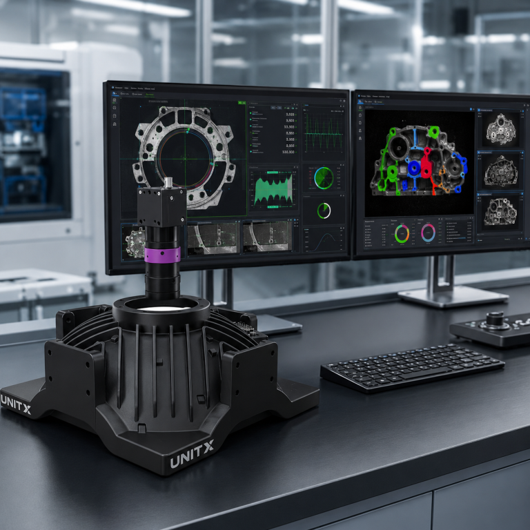
6. Software-Defined Illumination
Software-defined lighting systems use independently controllable LED arrays — often 32 or more individually addressable channels — to generate any illumination pattern under software control.
Rather than selecting a fixed lighting geometry for a specific application, the system cycles through multiple modes per capture cycle: brightfield, darkfield, coaxial-equivalent, oblique, and structured patterns can all be generated by the same hardware in sequence, with a different image captured under each condition. The results are composited by the AI processing system, which selects the highest-information frame for each defect category.
As Machine Design reports on advanced LED control techniques, programmable LED arrays allow individual segments to be controlled independently, enabling different intensity patterns across the illuminated area — highlighting specific features, creating uniform illumination, or optimizing contrast for different surface materials within the same inspection setup. OptiX cycles through 50 lighting modes per second across 32 channels, enabling this multi-mode composite imaging at 1 m/s fly capture speeds.
This approach eliminates the traditional requirement to specify and fix a single lighting geometry during system commissioning — a significant operational advantage in high-mix manufacturing environments with frequent part changeovers.
How to Match Lighting Technique to Your Inspection Application
| Defect or Feature Type | Recommended Technique | Why |
| Micro-scratches on polished metal | Darkfield | Scatter from scratch edge creates bright contrast on dark background |
| Dimensional measurement / presence-absence | Backlighting | Maximum edge contrast, subpixel measurement accuracy |
| Print, barcode, label inspection | Brightfield | Surface-parallel reflection creates natural text contrast |
| PCB solder pads, semiconductor wafers | Coaxial | Eliminates directional shadow on flat, reflective surfaces |
| Height, warp, flatness measurement | Structured Light | Pattern deformation encodes Z-axis geometry |
| High-mix parts, multiple defect types | Software-Defined | Multi-mode cycling eliminates per-part reconfiguration |
For most single-application, single-material inspection stations, one of the first five techniques provides the optimal solution. For high-mix manufacturing environments — where part geometry, material, and defect type change frequently — software-defined illumination is the only approach that avoids the operational overhead of manual lighting reconfiguration.
Explore how the OptiX imaging system implements software-defined lighting for AI visual inspection applications across automotive, battery, and semiconductor lines. See how it connects to CorteX AI for real-time defect classification and closed-loop quality control.
Practical Setup Considerations
LED Is the Standard for Production Vision Systems
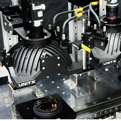
LED lighting has become the de facto standard for production machine vision, replacing fluorescent, halogen, and xenon sources in the vast majority of new installations. The reasons are well-established: LED sources provide stable illumination intensity over their operational life (unlike fluorescent, which dims with age and temperature), support strobe modes that freeze part motion at high production speeds, and enable the fine-grained intensity control that software-defined systems require.
For high-speed fly capture applications — where parts move at 300 mm/s to 1 m/s past the camera — LED strobe duration control is critical for eliminating motion blur without reducing illumination intensity below detection threshold.
Account for Production Environment Light Contamination
Machine vision illumination specifications that appear adequate in isolation can fail in production when ambient light contamination — overhead factory lighting, neighboring station illumination, or windows — introduces intensity variation that the AI model was not trained to handle.
Standard mitigations include light-tight enclosures around the inspection station, UV or bandpass optical filters that pass only the illumination wavelength, and polarized lighting for highly reflective surfaces where glare elimination is required. Each of these should be specified as part of the system design rather than added as afterthought during commissioning.
Frequently Asked Questions
Can a single lighting technique handle all defect types on my production line?
Rarely. Most production inspection applications require at minimum two complementary illumination modes: a surface-revealing technique (darkfield or brightfield) for cosmetic defect detection and a dimensional technique (backlighting or structured light) for geometric feature verification.
Fixed-mode systems must choose which defect types to optimize for, whereas software-defined systems cycle through multiple modes per inspection cycle, eliminating this tradeoff. The right solution for your specific application depends on defect profile complexity, part geometry, and production speed constraints — a UnitX expert can evaluate your inspection requirements.
Why does my AI model perform poorly when production lighting changes?
AI defect detection models learn the statistical relationship between pixel patterns and defect labels in the training dataset. If production lighting drifts from training conditions — due to LED aging, fixture misalignment, or ambient light changes — the pixel patterns associated with each defect type change in ways the model was not trained to handle.
The solution is either to train with augmented data that covers the expected range of lighting variation or to stabilize illumination through hardware controls (such as strobe intensity monitoring and optical isolation enclosures). Software-defined lighting systems with feedback-controlled intensity monitoring address the hardware side of this problem automatically.
Explore UnitX resources and case studies for documented examples of production illumination stability across multi-year deployments.
Is structured light slow enough to be a bottleneck on fast production lines?
Traditional structured light systems require part dwell time — typically 100–500ms — for pattern projection and capture, which can create a cycle-time bottleneck on lines running at more than a few hundred parts per minute.
Modern systems that implement structured light via software-controlled LED arrays (rather than mechanical pattern projection) can reduce this to 20–50ms per capture, and fly capture implementations extend structured light capability to moving parts. At 6 × 3D reconstructions per second, the OptiX system maintains structured light depth profiling at production line speeds without requiring part stop-motion staging.