Ask any machine vision engineer where most inspection failures originate, and the answer is almost always the same: lighting. The machine vision lighting market was valued at $1.87 billion in 2024 and is projected to reach $3.65 billion by 2032, a trajectory that reflects how central illumination has become to modern, AI-powered manufacturing quality control. Yet lighting selection remains one of the most underdisciplined steps in inspection system design — most teams finalize camera and software choices before seriously evaluating light geometry or spectral options.
This guide compares the seven most commonly deployed machine vision lighting solutions for high-speed inspection lines. Each approach has distinct strengths, trade-offs, and optimal applications. Understanding these distinctions can mean the difference between an inspection system that detects 99.9% of defects at 1 m/s and one that misses subtle surface variations under suboptimal illumination conditions.
Key Takeaways
- Lighting determines inspection outcomes more than any other hardware component — no camera or algorithm can compensate for poor illumination.
- There is no universal “best” lighting type — the optimal solution depends on surface reflectivity, defect class, part geometry, and line speed.
- Software-defined lighting (SDL) is emerging as the AI-era solution to multi-defect, high-speed inspection challenges by cycling through 50+ modes per second without mechanical adjustments.
- Dark-field and coaxial lighting are routinely underestimated — for reflective or textured surfaces, they can outperform ring lights by a significant margin.
- Integration with AI inference changes the lighting equation: AI systems extract more value from lighting diversity than rule-based systems, making programmable illumination an investment multiplier.
Why Lighting Is the Make-or-Break Variable in High-Speed Inspection
The Physics of Motion Blur and Contrast Failure
At inspection speeds exceeding 300 mm/s, even a 5 ms exposure window introduces motion blur unless the light source can strobe at sufficient intensity within the camera’s shutter window. Standard illumination techniques — back lighting, diffuse bright-field, directional bright-field, and dark-field — all interact differently with part motion, and the wrong choice at high speed produces inconsistent pixel intensity that can defeat even the best deep learning models.
The physics is straightforward: light that takes 10 ms to stabilize after a trigger is unusable at 1 m/s line speeds. Manufacturers evaluating machine vision lighting for high-speed applications must account for strobe response time, trigger jitter tolerance, and heat dissipation under continuous operation — not just lux output at a given distance. The position and type of lighting are key to maximizing contrast of inspected features while eliminating background interference that generates false rejects.
How Software-Defined Lighting Changes the Equation
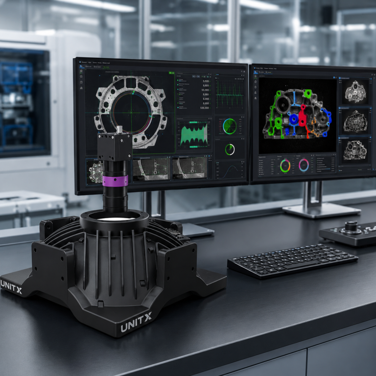
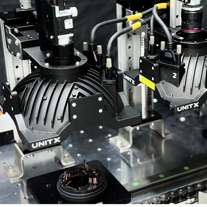
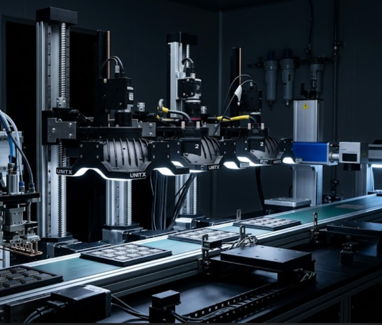
Traditional lighting architectures require engineers to physically reconfigure lights when switching between part types or defect classes — a process that can consume hours of setup time per changeover. Software-defined lighting systems replace this with programmable, multi-channel illumination that switches modes through software commands, enabling a single OptiX installation to cover ring, coaxial, dark-field, and structured-light modes without moving a single fixture.
The OptiX imaging system implements 32-channel software-defined lighting that cycles through 50 lighting modes per second — making it possible to capture multiple illumination perspectives of a single part during one pass. This dramatically improves defect coverage for complex surface geometries in automotive, battery, and semiconductor inspection applications.
7 Machine Vision Lighting Solutions Compared
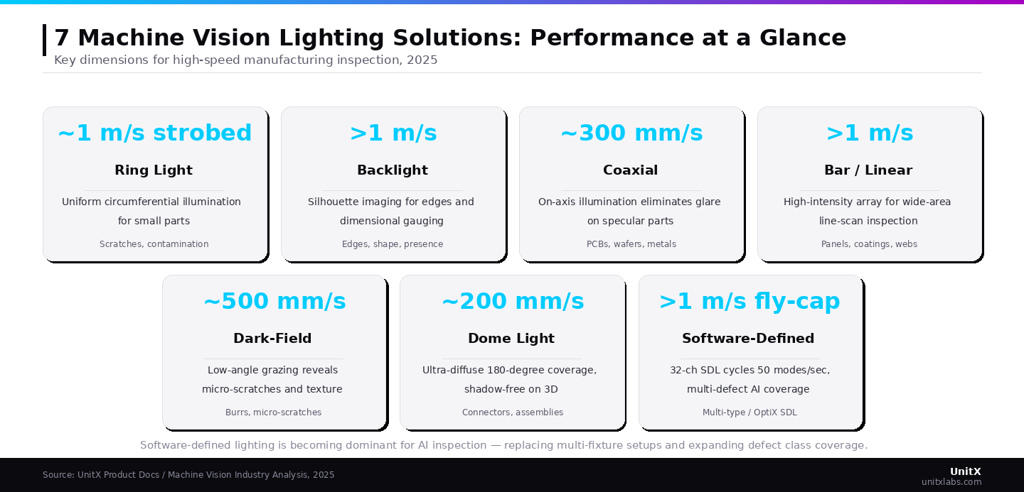
1. Ring Light — Universal Workhorse for General Inspection
Ring lighting mounts concentrically around the camera lens, providing uniform circumferential illumination across the inspection target. Better lighting leads to better image quality, resulting in more accurate analysis and reduced system errors — ring lights achieve this through their symmetric geometry, which eliminates directional shadows that can cause false positives on non-defective features.
Ring lights perform best for small part inspection at moderate line speeds (typically ≤500 mm/s), including scratches, surface contamination, and general-purpose quality checks. Their compact form factor simplifies integration into tight machine guarding envelopes. The limitation: at grazing angles or on reflective metal surfaces, ring illumination produces specular hotspots that obscure the very defects it is meant to detect. For these applications, coaxial or dark-field configurations perform substantially better.
Best for: Small parts, plastic components, general surface defects, contamination detection
Speed range: Optimal ≤500 mm/s; strobed versions extend to ~1 m/s
Limitation: Reflective surfaces produce glare; limited depth-of-field on 3D parts
2. Backlight — Precision Edge and Dimensional Gauging
With the light source positioned behind the part and the camera facing it, backlighting creates a high-contrast silhouette ideal for dimensional measurement and edge detection. It is particularly well-suited for gauging stamped metal blanks, verifying connector pin presence, and inspecting medical syringe bodies.
Backlighting achieves some of the highest inspection speeds because it relies on contrast between transmitted light and the part outline rather than surface reflection — a relationship that remains stable even at 1 m/s or above. The key constraint: backlight inspection is inherently surface-blind. It reveals shape and dimensional information but cannot detect surface scratches, coating defects, or contamination that front-light configuration would capture.
Best for: Dimensional verification, edge detection, presence/absence checks, medical device inspection
Speed range: High-speed capable ≥1 m/s with proper strobe timing
Limitation: Cannot detect surface defects; requires careful part staging
3. Coaxial Light — Reflective Surface Specialist
Coaxial illumination directs light along the same optical axis as the camera lens using a beam splitter. This produces glare-free imaging, making it ideal for inspecting reflective specular surfaces such as polished metals, PCBAs, and mirror-finish components.
In electronics and semiconductor manufacturing, coaxial lighting is the preferred solution for inspecting PCBAs, wafer surfaces, and connector pin planarity — applications where ring or bar lights would create hotspot reflections that mask defect signals. The trade-off is system complexity: beam splitters reduce effective light intensity, and coaxial setups require more precise mechanical alignment than ring configurations.
Best for: PCBAs, polished metals, semiconductor wafers, connector pins
Speed range: Moderate, typically ≤300 mm/s due to intensity constraints
Limitation: Intensity loss through beam splitter; alignment-sensitive
4. Bar Light — High-Speed, Wide-Area Coverage
Bar lights deploy a high-density linear array of LEDs to deliver intense, uniform illumination across large inspection fields. They are the workhorses of web inspection, line-scan camera systems, and high-throughput assembly lines where the part spans a wider field of view than a ring light can uniformly cover.
The directional nature of bar lights enables angular illumination control — mounting them at low angles relative to the part surface creates a dark-field effect for surface texture and relief detection, while high-angle mounting produces bright-field illumination for contrast-based detection. Bar lights routinely achieve inspection speeds exceeding 1 m/s when paired with strobed drivers and line-scan cameras.
Best for: Wide-area surfaces, line-scan systems, web inspection, large automotive panels
Speed range: High-speed capable ≥1 m/s
Limitation: Directional — shadows may form on 3D parts depending on angle
5. Dark-Field Light — Micro-Defect and Surface Texture Detection
Dark-field lighting positions the illumination source at a very low angle relative to the inspection surface: typically 10–30° from horizontal — so that only scattered light from surface irregularities reaches the camera. The background appears dark, while surface features such as micro-scratches, etching, embossed marks, and particle contamination appear as bright signals against that dark background.
Dark-field is the technique of choice for detecting defects that ring or bright-field lighting makes invisible: subtle surface abrasions on polished automotive components, fine burrs on machined gear teeth, and porosity in weld seams. The limitation is part geometry — dark-field illumination requires relatively flat surfaces with consistent topology; curved parts scatter the baseline illumination unpredictably, creating false positives.
Best for: Micro-scratches, surface texture, embossed marks, fine surface relief detection
Speed range: Moderate, typically ≤500 mm/s
Limitation: Requires flat or consistently curved surfaces; setup-sensitive
6. Dome Light — Complex 3D Part Illumination
Dome lights use LEDs arranged around the periphery of a hemispherical diffusion chamber, flooding the inspection target with ultra-diffuse light from angles spanning nearly 180°. The result is virtually shadow-free illumination that renders all surfaces of a 3D part with consistent brightness — the opposite extreme of dark-field geometry.
Dome lighting is particularly effective for inspecting connector assemblies, medical device components, and textured injection-molded parts, where directional lighting creates spurious shadows that hinder automated classification. The primary constraint is physical size: effective dome lights must be approximately twice the diameter of the field of view and positioned close to the part, limiting application in tight conveyor geometries.
Best for: Complex 3D parts, textured surfaces, connector assemblies, medical devices
Speed range: Lower-speed applications, typically ≤200 mm/s
Limitation: Large physical footprint; requires close proximity to part
7. Software-Defined Lighting (SDL) — AI-Era Multi-Defect Coverage
Software-defined lighting represents the transition from static hardware configurations to programmable, adaptive illumination architectures. Rather than selecting a single lighting modality and accepting its trade-offs, SDL systems drive multiple independent LED channels at precisely timed intensities and angles — cycling through ring, dark-field, coaxial, and structured-light modes within a single fixture and a single part transit.
The value proposition of SDL in AI visual inspection is multiplicative. Traditional rule-based systems benefit modestly from additional lighting perspectives. AI inference systems built on deep learning — such as the UnitX AI visual inspection system — extract substantially greater defect signals from multi-angle illumination diversity, because neural networks can learn which lighting channel reveals each defect class and fuse signals that no single channel captures reliably.
OptiX’s 32-channel SDL architecture cycles through 50 lighting modes per second, enabling 1 m/s fly-capture inspection without mechanical staging. For automotive powertrain components, where a single part may exhibit dimensional defects (best detected with backlighting), surface abrasions (dark-field), and contamination (ring/diffuse), SDL eliminates the need to choose. A single pass captures all defect types simultaneously. Setup time for new part programs drops from traditional multi-hour calibration cycles to under 30 minutes (UnitX customer data, 2025).
 Software-defined lighting is becoming the dominant choice for AI inspection lines, replacing manual multi-fixture setups and driving a shift in how defect coverage is achieved.
The broader machine vision industry reflects this trajectory: the global machine vision market is projected to reach $23.63 billion by 2030, driven substantially by AI integration that demands richer illumination inputs to achieve its full detection potential.
Best for: Multi-defect AI inspection, high-variation parts, rapid changeover lines
Speed range: High-speed capable ≥1 m/s with fly-capture
Advantage: Single installation covers ring, dark-field, coaxial, and structured-light modes
How to Choose: Matching Lighting to Your Inspection Requirements
Decision Matrix: Speed, Surface Type, and Defect Class
The selection logic for machine vision lighting follows three primary axes: (1) line speed and strobe response requirement, (2) surface reflectivity and geometry, and (3) the defect class to be detected.
| Lighting Type | Max Speed | Surface Type | Primary Defect Class | AI Synergy |
| Ring Light | ~1 m/s (strobed) | Matte, plastic, ceramic | Surface contamination, scratches | Moderate |
| Backlight | >1 m/s | Opaque/transparent | Edges, dimensional, presence | Moderate |
| Coaxial | ~300 mm/s | Specular / reflective | PCB, wafer, polished metal | High |
| Bar / Linear | >1 m/s | Wide-area, flat panels | Surface, coating, line-scan | High |
| Dark-Field | ~500 mm/s | Flat, matte, machined | Micro-scratches, burrs, texture | Very High |
| Dome | ~200 mm/s | Complex 3D, textured | Assembly, 3D surface defects | Moderate |
| Software-Defined | >1 m/s | All surface types | Multi-class, AI-powered | Maximum |
Integration Considerations for AI-Powered Inspection
When deploying AI-powered visual inspection, lighting choice compounds over time in ways that static, rule-based systems do not experience. A deep learning model trained on ring-light images will underperform if the light degrades, shifts in angle, or during a line upgrade — a problem that software-defined lighting eliminates by embedding the illumination profile as a software-controlled parameter rather than a fixed mechanical configuration.
Three practical integration considerations apply regardless of lighting type: First, strobe triggering must be synchronized to camera exposure at microsecond precision to avoid image-to-image intensity variation that can degrade AI model consistency. Second, thermal management determines long-term stability — LEDs that drift in color temperature or intensity over an 8-hour shift introduce systematic false rejection variance. Third, the LED driver architecture must support PWM control for programmable intensity, which is required for multi-channel SDL configurations. Talk to a UnitX expert about configuring OptiX’s software-defined lighting for your specific part type and line speed to avoid the most common integration pitfalls.
The LED machine vision lighting segment alone was valued at $1.13 billion in 2024 and is growing at 13.6% CAGR, reflecting the manufacturing sector’s broader shift toward AI-compatible, programmable illumination as the industry transitions from fixed-configuration legacy setups.
Frequently Asked Questions
What is the most important factor when selecting machine vision lighting for high-speed inspection?
Strobe response time and intensity stability are the most critical factors at high line speeds. At 1 m/s, a 10 ms exposure window means the light must reach full intensity and extinguish cleanly within that window to avoid motion blur and intensity variance. A light with the right geometry but inadequate strobe performance will produce inconsistent results, regardless of downstream algorithm sophistication. After confirming strobe capability, match the lighting geometry to your surface type: specular surfaces require coaxial or SDL; micro-defect detection requires dark-field; general surface inspection is well-served by ring or bar configurations.
Can a single lighting solution cover multiple defect types?
Not reliably with traditional fixed-configuration lighting. Different defect classes require different illumination geometries: a micro-scratch that dark-field lighting renders clearly is nearly invisible under ring illumination, and vice versa for dimensional edge features. Software-defined lighting is the only single-installation solution that addresses multiple defect classes simultaneously by cycling through illumination modes within a single part transit — a capability that becomes especially powerful when paired with AI inference engines capable of fusing multi-channel image signals.
How does lighting selection affect AI model training?
Lighting selection determines which defect features are visible in training images. A model trained on images from a single illumination angle will not generalize well to defect instances that only appear clearly under a different angle. Multi-channel SDL captures 5–15 image perspectives per part transit, giving AI models a richer signal base and significantly improving recall for low-contrast defect types. The practical implication: teams that select SDL at system design time require fewer labeled defect images to train effective models — a meaningful advantage in low-defect-rate production environments where samples are scarce. FleX-Gen further addresses this by generating synthetic defect images from as few as 3 real samples when production-line defect examples are limited.
What lighting type works best for battery cell inspection?
Battery cell inspection typically requires a combination of approaches depending on defect class: backlighting for electrode overhang dimensional verification, dark-field for surface contamination on separator layers, and coaxial or SDL for tab laser weld quality inspection. Because battery inspection involves multiple part geometries and defect types in the same production line, software-defined lighting that adapts to each inspection station without mechanical reconfiguration provides the best practical balance of coverage and throughput. See UnitX’s battery inspection solution for deployment data on tab weld and electrode inspection configurations.
How often does machine vision lighting need to be recalibrated?
Traditional fixed LED lighting typically requires intensity recalibration every 3–6 months as LEDs degrade, along with full setup recalibration when switching part numbers. Software-defined lighting, controlled through closed-loop drivers, maintains stable output by automatically compensating for LED aging and temperature drift, significantly extending calibration intervals. High-quality LED lighting should prioritize consistent intensity across production shifts, and systems with active feedback control measurably outperform passive configurations in long-run inspection stability.