Every quality engineer who has deployed a 2D machine vision system on a polished metal or ceramic surface knows the problem: the system detects defects that are not there. Specular reflections, surface microtopography, and lighting geometry interact to create pixel intensity patterns that 2D classifiers cannot reliably distinguish from actual scratches, pits, or contamination.
Without height or depth information, 2D detection systems are frequently susceptible to natural light variations, shadows, water, and oil stains that produce false defect signals, and there is no algorithmic fix in a 2D system for a problem that is fundamentally caused by missing geometric information.
2.5D imaging adds a per-pixel depth dimension, a Z-axis height map of the surface — that resolves this ambiguity. That suspicious dark region in the 2D image: does it have any depth deviation? If not, it is a reflection artifact, not a defect. That other region with a 40 µm depression: that is a real pit.
The global machine vision market is projected to grow from $15.83 billion in 2025 to $23.63 billion by 2030, with 3D and 2.5D imaging among the fastest-growing segments as manufacturers seek the depth data required for reflective surface inspection. This article explains how 2.5D imaging technology works, where it delivers superior results over 2D, and how to evaluate whether your inspection application requires depth data.
Key Takeaways
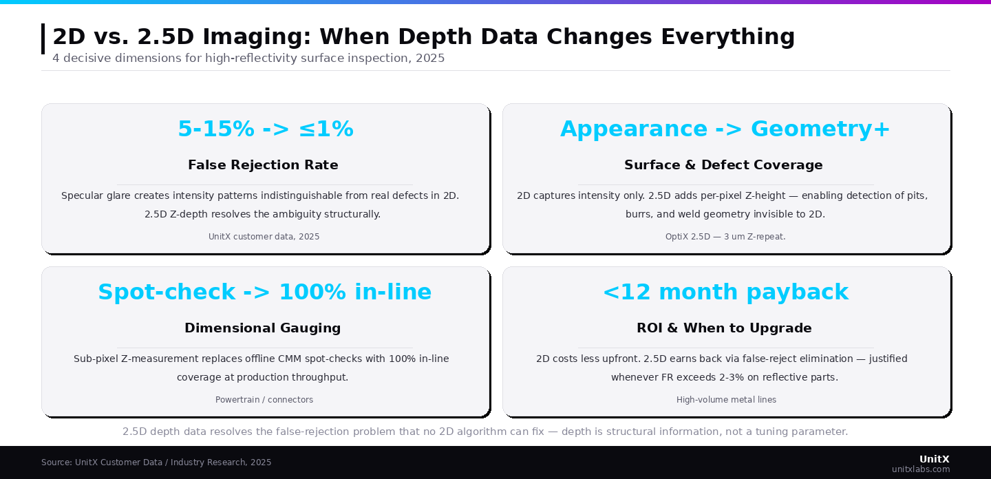
- 2D inspection fails on reflective surfaces — false rejection rates of 5–15% are common on polished metals, coated components, and ceramic parts when depth data is absent.
- 2.5D imaging adds a per-pixel Z-axis height map to the standard 2D intensity image, enabling AI models to distinguish appearance artifacts from geometric defects with high confidence.
- Structured light projection is the dominant 2.5D technique in production environments — it is fast, non-contact, and achieves sub-millimeter depth resolution suitable for most industrial inspection requirements.
- 3 µm Z-axis repeatability enables reliable detection of pits, burrs, and surface deformations that 2D imaging cannot classify consistently.
- 2.5D is not always necessary — for flat, matte surfaces with color-distinguishable defects, 2D inspection is often sufficient and more cost-effective. The key decision framework are surface reflectivity and defect geometry.
The Limits of 2D Inspection on Modern Manufacturing Surfaces
What 2D Imaging Captures — and What It Cannot
Standard 2D machine vision captures a two-dimensional projection of a part’s surface: intensity values (in grayscale or color) at each pixel position. This is sufficient for a wide range of inspection tasks — presence/absence checks, barcode reading, label verification, color inspection, and flat-surface cosmetic defects such as contamination, staining, and printing errors on matte or low-reflectivity surfaces. In these applications, 2D delivers excellent results at low cost and high throughput.
The failure mode arises from geometric ambiguity on reflective or topographically complex surfaces. When a polished aluminum part reflects an overhead light fixture as a bright spot, the 2D image shows a high-intensity region with sharp edges — indistinguishable from a raised burr or bright inclusion using intensity information alone. When a low-gloss surface contains a subtle pit 30 µm deep, the pit appears as a slightly darker region in the 2D image — indistinguishable from a shadow or a surface texture variation at that scale.
With the advent of 2.5D depth sensors, building geometrically informed detection systems has become increasingly important — 3D dimensional shape information provides critical cues for object recognition and defect classification that 2D intensity images fundamentally cannot capture.
The False Rejection Cost on Reflective Surfaces
Industry data on 2D inspection of reflective surfaces is clear: systems without depth information report false positive rates that can reach 5–15% on polished metals, coated components, and complex geometries. For a production line running 10,000 parts per shift, this represents 500–1,500 false rejects per shift — each requiring manual re-inspection to determine whether the rejection was genuine. The labor cost of re-inspecting false rejects frequently exceeds the labor savings that automated inspection was supposed to deliver.
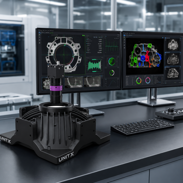
The OptiX imaging system implements 2.5D imaging with 3 µm z-repeatability at a 500 mm field of view, sufficient to detect sub-millimeter pits, burrs, and deformations that are critical defects in precision-machined and stamped metal parts. This depth resolution enables AI models to definitively classify surface anomalies by their geometric properties rather than relying on ambiguous intensity signals alone.
How 2.5D Imaging Works: From Structured Light to Depth Maps
Structured Light Projection: The Dominant Industrial Method
The most widely used technique for 2.5D depth measurement in production environments is structured light projection. A projector emits a precisely known light pattern — typically parallel sinusoidal fringe patterns or binary-coded sequences — onto the part surface. A camera positioned at a calibrated angle captures how the projected pattern deforms as it wraps around the surface’s geometry. Where the surface is flat and at the nominal height, the pattern appears as projected. Where there is a pit, bump, or step, the pattern shifts laterally in the captured image. Structured light illumination is widely used for surface defect detection due to its advantages in speed, precision, and non-contact capabilities.
Triangulation geometry converts the observed pattern shift into absolute height measurements at each pixel. The result is a depth map — a 2D image where each pixel value represents the Z-axis height of the surface at that location, rather than its intensity. Fusing this depth map with the standard 2D intensity image gives the AI inspection model both appearance and geometric information for every point on the surface.
The Z-Axis Resolution Question: How Much Depth is Enough?
Not all 2.5D systems achieve the same Z-axis resolution, and the required specification depends on the defect class being detected. General surface profile inspection for dimensional verification typically requires 10–50 µm depth resolution. Detection of fine surface pits, micro-burrs, and shallow depressions — the defect classes that most justify the investment in 2.5D over 2D — requires 3–10 µm Z-axis resolution. Sub-micron depth resolution is achievable with interferometric methods but is neither required nor practical for production-line inspection speeds.
The OptiX imaging system‘s 3 µm z-repeatability at a 500 mm field of view places it in the high-resolution category for inline production inspection — sufficient for demanding defect classes in precision automotive components, semiconductor packaging, and battery electrode inspection. This level of resolution enables reliable detection of sub-pixel-scale surface anomalies that even advanced 2D systems with sophisticated AI models cannot classify with acceptable false rejection rates.
Handling High-Reflectivity Surfaces: The Key Technical Challenge
High-reflectivity surfaces create saturation artifacts in structured light depth mapping — the projector fringes overexpose in bright regions, causing depth measurement to fail precisely where inspection is most needed. High-reflectance surfaces produced overexposed highlights that obscure the projection fringe, requiring polarization techniques or multi-exposure fusion to achieve precise 3D reconstruction.
Industrial 2.5D systems address this through several techniques: polarized structured light (projector and camera with crossed polarizers to suppress specular return), multi-exposure fusion (combining multiple captures at different intensities to avoid saturation in any single capture), and adaptive fringe design (using fringe frequencies optimized for the surface’s reflectivity profile). Polarization-based structured light systems achieve correct depth information even on surfaces where stereo vision produces incorrect depth judgments due to specular reflections.
2.5D imaging fundamentally shifts the false rejection equation on reflective surfaces — making it a decisive upgrade for polished metal, weld, and semiconductor inspection.
Where 2.5D Imaging Delivers Measurable ROI Over 2D
Precision Machined Automotive Components
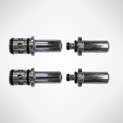
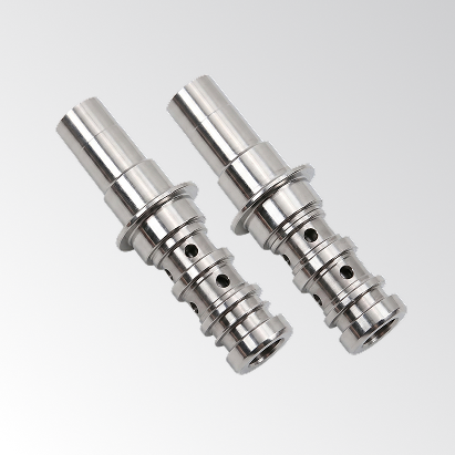
Gear teeth, powertrain housings, bearing surfaces, and precision fasteners represent automotive inspection applications that are particularly well suited to 2.5D imaging. These parts are typically machined to tight dimensional tolerances (±5–50 µm on critical features), have low surface roughness that makes reflective artifacts inevitable under standard illumination, and must be inspected for defect classes — burrs, micro-cracks, and machining marks — that are defined by their geometry as much as their appearance.
2D inspection of machined aluminum powertrain parts commonly produces 8–12% false rejection rates due to reflection-induced artifacts. Implementing 2.5D imaging reduces false rejection to under 1% (FR ≤ 1% specification) while maintaining detection of genuine dimensional and surface defects. The throughput improvement from eliminating false-reject re-inspection more than justifies the system cost difference in high-volume applications. UnitX automotive inspection solutions document this pattern across multiple Tier-1 automotive deployments (UnitX customer data).
Battery Electrode and Tab Inspection
EV battery cell manufacturing requires inspection of electrode sheets, separators, and tab welds at micron-scale precision. Electrode overhang uniformity, coating continuity, and tab weld geometry are all dimensional characteristics that 2.5D imaging detects reliably — and that 2D imaging struggles to capture due to the reflective surfaces of aluminum and copper current collectors.
Tab laser weld inspection is a specific application where 2.5D provides clear value. Weld penetration depth, spatter height, and crown geometry are all geometric characteristics that determine weld quality and predict thermal performance, but that do not manifest as reliable intensity anomalies in 2D images. Battery tab weld inspection with AI-powered 2.5D imaging captures these geometric weld quality indicators at production throughput, enabling detection of weld defects that can thermally or electrically compromise battery cell performance.
Semiconductor Packaging and Substrate Inspection
Semiconductor packaging inspection requires sub-micron flatness measurement on bonding pads, underfill void detection in flip-chip packages, and solder bump height uniformity verification — all fundamentally geometric measurements that cannot be derived from intensity images alone. 2.5D imaging provides the depth resolution required for these measurements at production throughput, replacing slower offline CMM or SEM verification for 100% inline quality control.
UnitX semiconductor inspection solutions integrate 2.5D imaging with pixel-level AI segmentation for combined appearance and geometric inspection at production speed. This combination — not 2.5D or 2D alone, but both fused — provides the complete defect signature needed for reliable semiconductor packaging QC.
2D vs. 2.5D Decision Framework
| Inspection Scenario | Recommended Approach | Key Reason |
| Flat surface, color-distinguishable defects | 2D sufficient | No reflective ambiguity; lower cost |
| Polished metal, chrome, or mirror-finish surface | 2.5D required | FR 5–15% without depth data |
| Dimensional gauging, burr detection | 2.5D required | Geometry cannot be measured from intensity |
| Label / barcode / print verification | 2D sufficient | Pattern-based detection; no depth needed |
| Weld quality inspection | 2.5D preferred | Penetration depth is geometric characteristic |
| Battery electrode coating inspection | 2.5D + 2D combined | Both appearance and thickness verification |
| Semiconductor bump/pad flatness | 2.5D required | Sub-micron flatness is geometric, not visual |
Frequently Asked Questions
What is the difference between 2.5D and true 3D imaging in industrial inspection?
2.5D imaging captures a per-pixel Z-axis height map from a single viewing direction — effectively a 2D image with one depth value per pixel. It provides surface topography information without a full volumetric model.
True 3D imaging, such as structured light scanning from multiple angles or confocal microscopy, reconstructs the complete geometry of a three-dimensional object, including undercuts, internal features, and surfaces not visible from a single viewpoint.
For most inline production inspection applications, 2.5D provides the depth information needed to classify surface defects accurately without the complexity, cost, or throughput penalty of full 3D volumetric scanning. UnitX inspection systems implement 2.5D imaging as the standard configuration for precision part inspection, with 3D options available for specific high-complexity applications.
How fast can 2.5D structured light imaging operate at production line speeds?
Modern structured light 2.5D systems achieve depth map acquisition at frame rates compatible with inline production inspection — typically 30–200 Hz for full-field depth maps, and higher rates for line-scan configurations.
The OptiX imaging system’s 1 m/s fly-capture capability combines software-defined lighting with 2.5D depth acquisition to inspect moving parts without the stop-and-measure cycle required by traditional 3D inspection systems. The key enabling technology is high-speed fringe projection with strobed illumination synchronized to the camera shutter — the same strobe timing requirements used in high-speed 2D inspection apply to 2.5D, with the additional requirement that the fringe pattern must be fully projected and acquired within each exposure window.
Talk to a UnitX expert about 2.5D inspection for your application
Not every application benefits equally from 2.5D imaging, and the cost difference between 2D and 2.5D systems is significant. Evaluation should begin with your current false rejection rate for the specific surface type and defect class: if FR is above 2–3% and the surface is reflective or requires dimensional verification, 2.5D imaging will typically pay for itself through false reject elimination. If FR is already within specification on a matte surface with color-distinguishable defects, 2D inspection is likely sufficient.
Talk to a UnitX expert to evaluate your specific part, surface type, and defect class against the 2D versus 2.5D decision criteria before committing to system selection.