Every machine vision system built before the last decade shared a common constraint: the hardware determines what the camera can see. If a surface is reflective, you add a polarizing filter. If you need a different angle, you physically move the light. If the product changes, you rebuild the optical setup from scratch. The assumption underlying every step is that imaging is a hardware problem.
Software-defined imaging challenges that assumption at its core. It decouples the physical act of capturing light from the decisions about how that light is shaped, sequenced, and processed — shifting control into software that can be reconfigured in minutes without any physical changes. This article explains what that means technically, why it matters for manufacturing inspection, and how the underlying architecture works.
Key Takeaways
- Software-defined imaging separates illumination control from sensor hardware, allowing engineers to reconfigure light angles, exposure sequences, and image fusion algorithms in software rather than by adjusting physical components.
- The core capability gain is programmable multi-angle illumination — 32 independently controlled light channels can be triggered in any sequence, creating image data that fixed-hardware systems cannot physically capture.
- When combined with deep learning inference, software-defined imaging enables inspection accuracy that surpasses both human inspection and rule-based machine vision for complex surfaces, mixed materials, and high-mix production lines.
- Reconfiguration time drops from days to minutes when a production line switches product types, because the optical setup exists in software rather than in physical hardware arrangements.
The Problem with Fixed-Hardware Imaging
Why Traditional Machine Vision Hits a Physical Wall
Conventional machine vision systems are built around a fixed optical configuration: a camera, a lens, a light source at a fixed angle, and a rule-based algorithm that checks whether pixel intensity values cross a threshold. This architecture works reliably when the inspection task is simple, the surface is matte, and the product never changes. On modern production lines, none of those conditions hold and unchanged.
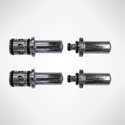
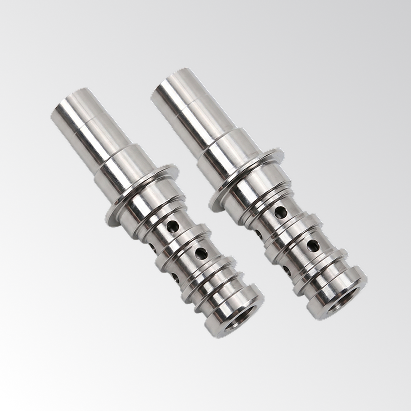
Reflective surfaces — polished metal, coated glass, chrome-plated components, battery electrode foil — scatter and redirect light unpredictably. A fixed LED ring illuminator, the workhorse of traditional machine vision, creates specular reflections that overwhelm the sensor exactly where defect detection is most critical. Engineers respond by adding polarizers, diffusers, coaxial illuminators, or multiple camera angles. Each addition increases system cost, setup time, and the number of mechanical components that can drift out of calibration.
The deeper problem is that the optical configuration is permanently committed to a single product geometry. When the product changes — different dimensions, different surface finish, or a different defect profile — the entire optical setup must be rebuilt. NIST research on U.S. discrete manufacturing found that losses from preventable downtime and maintenance issues amounted to $119 billion annually, with establishments relying on reactive maintenance experiencing 3.3 times more downtime than those using predictive approaches — a gap that grows sharply in high-mix environments where optical reconfiguration adds to planned stoppage time. (NIST — Manufacturing Machinery Maintenance: Costs and Benefits)
What Rule-Based Algorithms Cannot Resolve
The algorithm layer of traditional machine vision inherits all the limitations of its fixed hardware input. A threshold-based rule — “flag any pixel brighter than value X in region Y” — can only detect what its original programmer anticipated. New defect types, surface aging, acceptable cosmetic anomalies, or even a different batch of incoming material can push a well-tuned system into unacceptable false rejection rates or, worse, undetected escapes.
Manufacturing engineers who have deployed traditional inspection systems are familiar with the maintenance burden: rules require constant manual adjustment by a vision specialist, and the adjustment process typically requires production downtime. The National Institute of Standards and Technology has published extensively on how rule-based quality systems in discrete manufacturing degrade in accuracy as product variety increases. (NIST Manufacturing Research)
What Software-Defined Imaging Actually Is
The Architectural Separation That Changes Everything
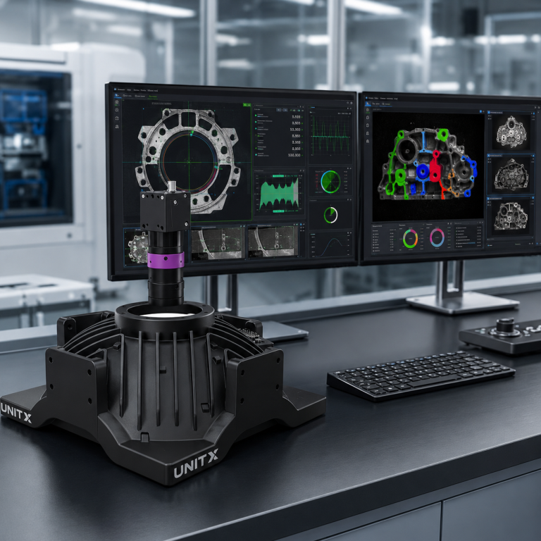
Software-defined imaging is an imaging architecture in which the illumination pattern, the image capture sequence, and image processing pipeline are all controlled programmatically rather than fixed by physical hardware configuration. The vision sensor remains a physical device, but what it captures — the angles, intensities, exposures, and sequences — is entirely determined by software parameters that can be changed without physical intervention.
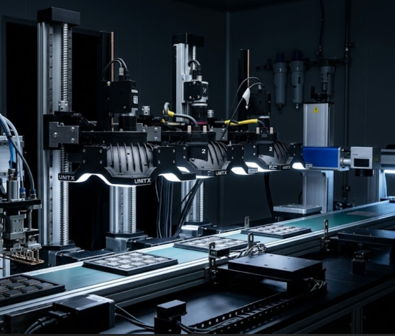
The practical implementation involves a multi-channel illumination controller.In the case of UnitX’s OptiX imaging system, this includes 32 independently controllable light sources that can fire in any combination, sequence, and intensity. Rather than physically swapping out a ring light for a dark-field illuminator when a new defect type emerges, engineers can fine-tune the “optical recipe” directly in software to achieve optimal contrast. A single inspection cycle may trigger eight different illumination configurations in rapid sequence, capturing a separate image frame for each at 1 m/s fly capture speeds.
The result is an imaging system optimized for continuous improvement and high-mix production. Because hardware constraints are removed, the software can continuously adapt to deliver the richest possible image data for AI analysis. By fusing these rapid, multi-angle frames, OptiX can also compute 2.5D topographical data. This computational approach achieves 3 μm Z-repeatability, allowing the system not only to identify surface anomalies but also to capture features such as scratch depth and raised particles — demonstrating how much data can be extracted when imaging is defined by software rather than fixed hardware.
Software-defined imaging separates each stage of the imaging pipeline into a configurable software layer. Changing product type or defect profile requires only a software update — no hardware modification.
Fly Capture: Inspection Without Stopping the Line
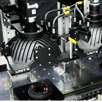
A critical capability enabled by software-defined illumination control is fly capture — the ability to acquire high-resolution, multi-angle images of parts moving at production line speed without stopping or slowing the conveyor. Traditional strobe-based systems can achieve this for simple tasks, but they are typically limited to a single illumination angle per trigger event.
Because a software-defined system like OptiX can synchronize multiple illumination channels with rapid sequential camera exposures, it can acquire a complete multi-angle image set in a single pass At 1 m/s line speed and 50-megapixel resolution, the system captures imagery with a level of detail and angular richness that would otherwise require multiple cameras and multiple strobe units in a conventional setup — each needing individual calibration and mechanical stability maintenance.
For high-volume manufacturers, this capability directly enables 100% inline inspection at full production throughput. UnitX’s OptiX system supports fly capture at 1 m/s, and CorteX inference throughput reaches up to 1,200 pieces per minute in optimized configurations. The entire inspection process — image capture, AI inference, and pass/fail decision— occurs within the cycle time budget of the production line.
How Software-Defined Imaging Integrates with AI Inspection
Why Richer Image Data Changes What AI Can Detect
Deep learning models for defect detection are only as capable as the image data they receive. A model trained on 2D images from a fixed-angle illuminator learns to detect defects as they appear under that specific lighting condition. When lighting drifts, when the product surface ages, or when a new defect type emerges that does not produce a distinctive 2D signature, the model fails — not because the algorithm is wrong, but because the input data is insufficiently informative.
Software-defined imaging changes the information density of each image frame. By fusing data from 32 illumination channels, the image presented to the AI model contains surface normal information, depth gradients, and reflectance anisotropy that a single-angle image cannot capture. This richer input allows deep learning segmentation — the approach used in CorteX — to distinguish between a scratch, a particle, a stain, and a true surface feature with far greater reliability than models operating on fixed-illumination 2D imagery.
The practical consequence is measurable in training data requirements. CorteX requires as few as 5 defect images per defect type to begin effective inference, because the multi-angle input provides enough discriminative information for the model to generalize from a small sample. Conventional vision AI systems typically require hundreds to thousands of labeled defect images to achieve comparable performance, because they must compensate for the information limitations of single-angle imaging with larger datasets. (IEEE — Deep Learning for Automated Surface Defect Inspection: A Survey)
The Role of Synthetic Data Generation
Even with software-defined imaging reducing training data requirements, rare defect classes remain a practical challenge. A defect that appears once in ten thousand parts cannot generate the labeled dataset needed for robust detection — and missing it is precisely what leads to costly quality escapes.
This is where generative AI becomes part of the inspection architecture rather than just a downstream tool. UnitX’s FleX-Gen platform generates synthetic defect images that are physically consistent with the multi-angle image characteristics produced by OptiX. These synthetic images augment real defect data, effectively expanding the training dataset for rare categories. FleX-Gen augmentation reduces false rejection rates by up to 9x by ensuring that CorteX is trained on a more balanced defect distribution, rather than one skewed by the natural rarity of specific defect types.
This combination — software-defined imaging providing richer real image data, and synthetic generation filling the rare-event gap — addresses both the data quality and data volume challenges that limit traditional inspection. For more detail on how the full inspection system integrates these capabilities, see the CorteX AI system documentation and the FleX-Gen synthetic data platform.
Reconfigurability: The Operational Advantage
What Changes When Illumination Lives in Software
For a manufacturing engineer running a high-mix production line, the most immediate impactful aspect of software-defined imaging is not just improved detection accuracy — it is the elimination of optical reconfiguration time when switching product types.
In a conventional machine vision deployment, a product changeover requires physical adjustment of light sources, repositioning of cameras, recalibration of the optical path, and re-validation of the inspection algorithm for the new product. For complex geometries, this process can take days of engineering time and production downtime. The cost is typically absorbed as a fixed overhead of flexible manufacturing — an accepted inefficiency.
With a software-defined system, the illumination profile, capture sequence, and image fusion parameters for each product type are stored as configuration files. A product changeover simply triggers a software configuration update. The physical hardware — lights, sensor, and enclosure — remains unchanged. Reconfiguration time drops from days to minutes, and no optical specialist is required on-site.
This reconfigurability is particularly valuable for Tier 1 automotive suppliers and battery manufacturers running mixed production schedules, where a single inspection station must handle multiple part variants across shifts. UnitX’s FleX platform manages these configuration profiles across multiple OptiX stations simultaneously, enabling centralized control of an entire inspection line’s optical parameters from a single interface. Learn more about how FleX enables this across multiple inspection points on the FleX product page.
Traceability as a Built-In Output
Because every inspection event is defined by software parameters, software-defined imaging systems generate a complete digital record of the exact optical configuration used for each inspected part. This traceability — which illumination channels were activated, at what intensity, in what sequence, combined with the AI inference result — creates a quality data record that traditional rule-based systems cannot produce.
This record integrates directly with Manufacturing Execution Systems (MES), closing the quality data loop. Process engineers can query the traceability database to determine whether a specific defect cluster correlates with illumination drift, material batch variation, or time-of-day patterns. The inspection system becomes an active source of process intelligence rather than a passive pass/fail gate. (McKinsey — Industry 4.0 and Real-Time Quality Data).
Where Software-Defined Imaging Applies
Industry Segments and Surface Types
Software-defined imaging’s advantages are most pronounced in scenarios where fixed-hardware vision struggles: highly reflective or specular surfaces, mixed-material assemblies, small defects on textured backgrounds, and high-mix production environments.
In battery manufacturing — one of the most demanding inspection environments — electrode foil, tab welding, and cell casing surfaces present reflective challenges that overwhelm fixed illuminators. The UnitX OptiX system’s 100x brightness advantage over conventional light sources, combined with programmable angle control, enables detection of micron-scale contamination and pinhole defects on foil surfaces that would be invisible to traditional illuminator. The battery industry solution covers this in detail.
In automotive component manufacturing, the variety of surface treatments — machined aluminum, chrome plating, painted assemblies, rubber seals, and glass — means a single inspection station may need to handle radically different optical profiles across a shift. Software-defined illumination makes this possible without hardware modification. The automotive inspection solution addresses this mixed-surface challenge directly.
Semiconductor packaging inspection presents a third application domain, where solder joint geometry, wire bond integrity, and substrate surface finish each require different illumination strategies. Centralizing these strategies into software profiles that can be deployed instantly makes software-defined imaging a natural fit for semiconductor back-end inspection. (IEEE — Semiconductor Inspection and Metrology Challenges)
| Industry | Surface Challenge | OptiX Capability |
| Battery / EV | Reflective electrode foil, tab weld inspection | Multi-angle eliminates glare; 3 μm depth for pinhole detection |
| Automotive | Mixed surfaces: chrome, painted, machined, rubber | Per-product software profile; changeover in minutes |
| Semiconductor | Solder joints, wire bonds, substrate coating | 2.5D topography; programmable angle per inspection type |
| General Precision Mfg. | High-mix, short run, frequent changeover | Software profiles eliminate optical rebuild downtime |
Implementation: What the Engineering Path Looks Like
From Proof of Concept to Production Deployment
A common misconception about advanced AI-powered inspection systems is that deployment requires a multi-month integration project. The UnitX FleX platform is engineered around a structured deployment path that targets Site Acceptance Testing (SAT) completion within days — not the weeks or months typical of custom machine vision integrations.
The deployment process begins with a sample inspection run against actual production parts, establishing the baseline defect library and validating detection performance against the agreed false acceptance rate (FA) and false rejection rate (FR) targets. Once the sample run meets specification — FA = 0% and FR ≤ 1% are the standard UnitX targets — the system is installed on the production line, MES integration is configured, and the production team is trained on the configuration management interface.
Post-deployment, the system continues to improve continuously. New defect types detected in production are flagged for labeling, and CorteX is retrained on updated data at defined intervals. FleX-Gen synthetic augmentation ensures that rare defect classes maintain model coverage even when real examples are limited. This continuous improvement loop transforms the system from a static inspection gate into a dynamic quality intelligence platform. See customer case studies for documented deployment timelines and performance outcomes.
Common Questions
Is software-defined imaging the same as 3D machine vision?
They overlap but are not equivalent. Software-defined imaging is an architectural approach that uses programmable multi-angle illumination and computational image processing. It can produce 2.5D depth information (as OptiX does), but its defining characteristic is reconfigurability, not dimensionality. Traditional 3D vision systems often use fixed structured-light projectors that cannot be reprogrammed without hardware changes.
How does software-defined imaging handle highly polished, mirror-finish surfaces?
Mirror-finish surfaces are where software-defined illumination provides its most decisive advantage. By sequencing illumination angles to avoid the specular reflection cone — which is predictable based on surface geometry — the system can capture surface information from angles that eliminate glare. This angular selection is controlled in software, allowing it to be tuned for each product surface without any physical hardware adjustments.
What is the minimum defect size that software-defined imaging can reliably detect?
Detection limits depend on sensor resolution, the FOV, defect contrast. OptiX supports up to 50 MP resolution and a maximum FOV of 500 mm, which corresponds to approximately 10 μm per pixel at full field. For smaller defects, the FOV can be reduced to achieve higher pixel density. The 3 μm z-repeatability in depth mode means that surface height variations at that scale are measurable, even if they are visible in a standard 2D image.
Can a software-defined imaging system replace our existing camera and lighting without changing the mechanical housing?
In most production environments, yes — OptiX is designed for inline installation and can integrate into existing line housings in standard configurations. The specific integration geometry depends on part size, conveyor configuration, and FOV requirements, which are evaluated during the pre-deployment sample inspection phase.