The working distance in a working distance machine vision system refers to the space from the front edge of the lens to the object’s surface where the image comes into sharp focus. Engineers consider working distance a primary factor in selecting lenses for any working distance machine vision system. This parameter shapes how the system captures clear and detailed images, influencing both field of view and magnification. A correct working distance ensures the working distance machine vision system delivers accurate imaging and reliable inspection results. Inadequate attention to working distance can lead to blurry images or missed defects, reducing the effectiveness of the entire system.
Key Takeaways
- Working distance is the space between the camera lens and the object, crucial for sharp focus and clear images in machine vision systems.
- Proper calibration of working distance ensures accurate imaging, helping detect defects and track objects reliably.
- Adjusting working distance affects field of view, magnification, and image resolution, so engineers must balance these for the best results.
- Lighting must match the working distance to maintain image clarity and contrast, which is vital for precise inspections.
- Careful planning and early calibration prevent common setup mistakes, improving system performance and avoiding costly redesigns.
Working Distance in Machine Vision
Definition and Measurement
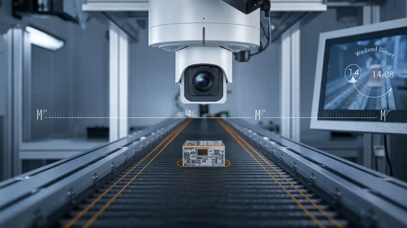
Working distance in a machine vision system describes the exact space from the front of the camera lens to the object being inspected. This measurement is essential for every machine vision system because it determines where the image comes into sharp focus. Engineers measure working distance physically using a ruler or tape measure. They also use optical formulas, such as the thin lens equation, to calculate the correct working distance for a specific lens and sensor combination.
Note: Accurate measurement of working distance ensures the system captures clear images for reliable detection and inspection.
To set up a working distance machine vision system, engineers often:
- Measure the size of the object and the available space.
- Select a lens based on the required field of view and magnification.
- Use calibration tools and calculators to confirm the working distance.
- Test the system with real objects and lighting to fine-tune the distance for the best image quality.
Calibration plays a key role in this process. It helps align the camera lens, image sensor, and object position for optimal imaging. Proper calibration ensures the system delivers sharp images, which is vital for defect detection, object tracking, and quality control.
Working Distance vs. Depth of Field
Working distance and depth of field are both important in machine vision optics, but they describe different concepts. Working distance is the fixed space from the lens to the object. Depth of field, on the other hand, is the range where the object stays in focus as it moves closer or farther from the lens.
Depth of field depends on factors like the lens aperture and design. A larger depth of field means the system can keep more of the object in focus, even if its position changes slightly. Working distance remains constant during calibration, while depth of field provides tolerance for small object movements.
| Concept | Explanation |
|---|---|
| Working Distance | Distance from lens to object; increasing it decreases image distance for a fixed focal length. |
| Image Distance | Distance from lens to image plane; inversely related to working distance. |
| Magnification | Changes with working and image distances; affects the size of the image on the sensor. |
| Depth of Field (DOF) | Range where object appears sharp; influenced indirectly by working distance through magnification. |
| Iris Aperture (f-number) | Controls DOF directly; stopping down (increasing f-number) increases DOF but reduces brightness. |
When engineers adjust working distance, they also affect magnification and depth of field. For example, increasing working distance can reduce magnification and change the depth of field. Calibration ensures the system maintains the right balance between these parameters for high-quality imaging and accurate detection.
Role in Machine Vision System
Working distance shapes the entire design of a machine vision system. It influences lens selection, field of view, and magnification. For example, a longer working distance may require a lens with a longer focal length to maintain the desired field of view. Calibration ensures the lens, image sensor, and object are all positioned correctly for the best optical performance.
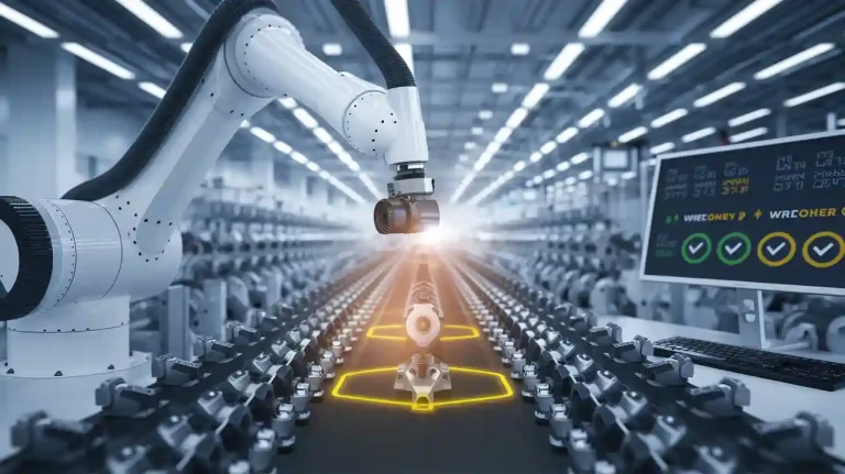
A well-calibrated working distance machine vision system supports many applications, such as defect detection, object tracking, and quality control. The system must match the working distance to the sensor size and required resolution to achieve clear images and reliable detection. During system design, engineers verify that the camera lens and sensor produce the correct field of view at the chosen working distance. They use calibration and testing to confirm that the system meets the needs of the application.
Tip: Early calibration and image evaluation at the intended working distance help identify and fix design issues before full system deployment.
System designers also consider space constraints and safety when setting working distance. They may use specialized lenses, such as telecentric lenses, to maintain consistent magnification across different object positions. Calibration tools help ensure the system delivers sharp, accurate images for all types of inspection and detection tasks.
A machine vision system with proper calibration and working distance supports high-quality imaging, precise detection, and reliable tracking. This approach leads to better results in industrial inspection, object tracking, and other machine vision applications.
Key Parameters and Impact
Field of View and Resolution
Working distance plays a central role in determining the field of view in any machine vision system. When engineers increase the working distance, the system can capture a larger area of the object or scene. The linear field of view (FOV) follows the formula FOV_l = 2 × (WD × tan(θ/2)), where θ is the angular field of view. This relationship means that as the working distance grows, the field of view expands, allowing the vision system to inspect bigger objects or wider areas. However, this increase comes with a trade-off. As the field of view becomes larger, the magnification decreases, and the image sensor captures less detail per unit area. This balance is crucial for applications like defect detection, where both coverage and detail matter.
Resolution in a machine vision system depends on several factors, including working distance, lens quality, and image sensor size. As working distance increases, the system collects fewer photons from the object, which reduces image resolution and localization accuracy. The table below summarizes these quantitative relationships:
| Parameter | Relationship / Effect | Example / Quantitative Detail |
|---|---|---|
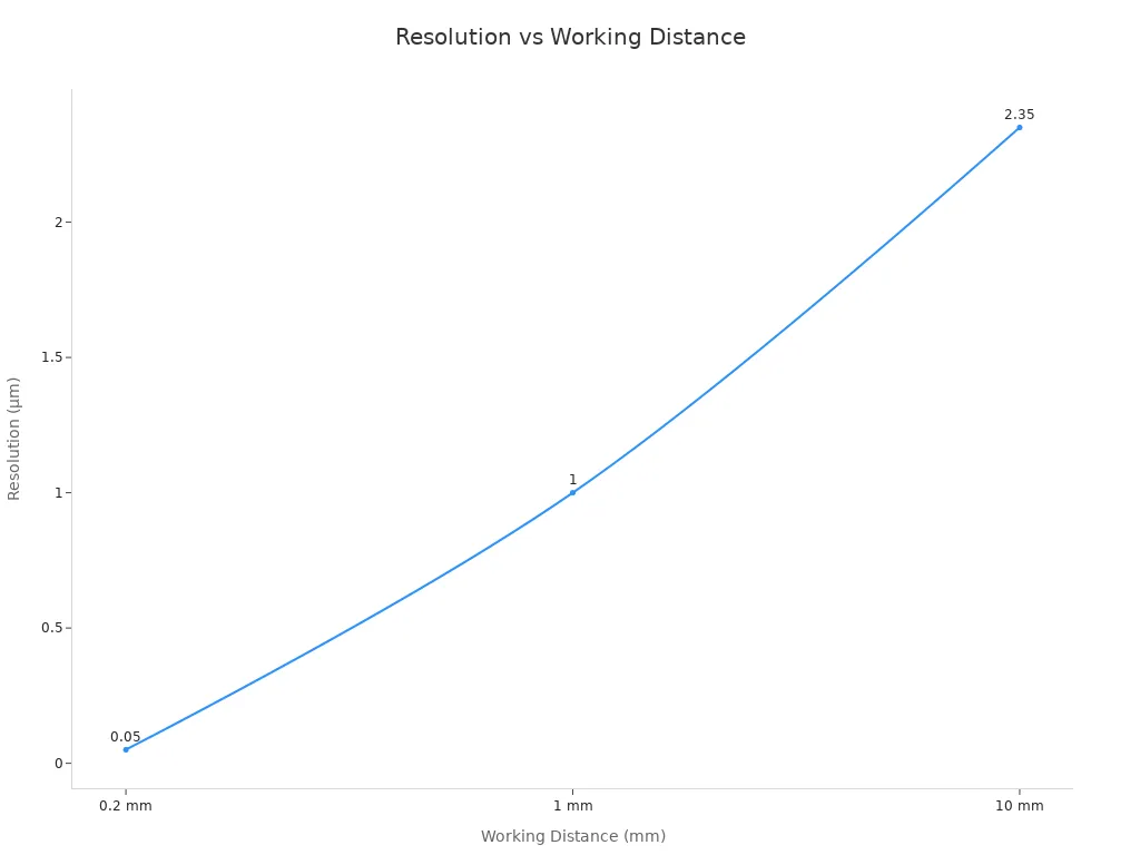
| Photon flux (I_flux) | Inversely with square of working distance (L) | Increasing L from 0.2 mm to 10 mm reduces photon flux by 2500x |
| Localization accuracy (σ_loc) | Inversely with sqrt of detected photons (N_det) | σ_loc worsens by 50x when L increases by 50x |
| Optical resolution (FWHM) | Proportional to localization accuracy (σ_loc) | Resolution degrades from ~50 nm to ~2.35 µm |
| Numerical aperture (NA) | Limited by working distance due to lens size | At 1 cm WD, NA ~ 0.2, limiting resolution |
| Advanced techniques | Can overcome low NA limitations | 4π illumination improves resolution at large WD |
Calibration ensures that the lens, image sensor, and object position work together to achieve the best possible field of view and resolution. Engineers must carefully select the working distance to balance the need for coverage with the requirement for high-quality imaging and precise detection.
Lighting and Image Quality
Lighting and image quality are closely linked to working distance in every machine vision system. The distance between the lens and the object affects how light reaches the surface and how the image sensor captures the scene. Longer working distances often require stronger or more focused lighting to maintain image clarity and contrast. Shorter working distances allow for more controlled and even illumination, which helps with defect detection and quality control.
Key points about lighting and image quality include:
- Proper lighting is essential for clear and accurate images, which enables precise detection of defects or anomalies.
- Lighting enhances contrast, making it easier to distinguish between objects and features within an image.
- Adequate lighting reduces noise and improves the signal-to-noise ratio, leading to more reliable and consistent results.
- Lighting can be used to control depth of field, ensuring critical areas remain in focus while others blur, improving image clarity.
- Different lighting solutions can be tailored to specific machine vision needs, providing versatility and adaptability.
- Longer working distances may require stronger or more focused lighting to maintain image clarity and contrast, while shorter distances allow for more controlled illumination.
Physical restrictions can also prevent optimal placement of lighting, especially in complex inspection setups. The fixture holding the workpiece or robotic equipment may block light, affecting illumination quality. Calibration helps engineers adjust lighting geometry and intensity to match the working distance, ensuring the system delivers high-quality imaging for defect detection and object tracking.
Space and Safety
Space and safety considerations influence the choice of working distance in a machine vision system. Engineers must ensure there is enough clearance for cameras, lighting, and other equipment. Limited physical access due to robotic arms or support structures can restrict the type and placement of lighting, as well as the working distance itself. Short working distances typically require less light, but may not provide enough space for safe operation or easy maintenance.
Ambient light sources, such as overhead lights or sunlight, can degrade image quality and detection accuracy. Engineers use calibration to manage these challenges by adding enclosures, filters, or strobing techniques. Surface characteristics, like shape and reflectivity, interact differently with light depending on the working distance and lighting geometry. For example, diffuse lighting can improve contrast on curved or shiny surfaces, while bright field lighting may work better for flat, matte objects.
Note: Early consideration of space and safety during system design helps avoid costly redesigns and ensures reliable operation in industrial environments.
Calibration remains a key step in optimizing space, safety, and optical performance. By carefully selecting and testing the working distance, engineers create a vision system that supports high-quality imaging, accurate detection, and safe, efficient operation for all applications, including defect detection, object tracking, and quality control.
Practical Use in Industrial Inspection
Application Scenarios
Industrial inspection covers a wide range of machine vision system uses. Printed circuit board inspection stands out as a common example. Industry standards, such as IPC-6012 and J-STD-001E, require specific magnification levels. These standards depend on the correct working distance to achieve sharp focus and clear image quality. Engineers use short working distances for high magnification tasks, such as defect detection on tiny components. Longer working distances help when monitoring large assembly lines or inspecting objects with varying heights.
- Working distance affects image clarity, focus, and depth of field.
- Short distances suit detailed inspections, like electronics or welds.
- Longer distances work best for broader views, such as conveyor belt inspections.
- Adjusting working distance changes the field of view and resolution, which is important for quality control.
Different inspection tasks need different setups. Stereo microscopes help with three-dimensional samples, while boom stand microscopes offer flexible positioning. The choice depends on the sample type and the inspection requirements. Optimizing working distance ensures precise detection and reliable imaging in all practical applications.
System Design Considerations
Engineers must consider several factors when designing a machine vision system for industrial inspection. Working distance plays a key role in lens selection. The lens type, sensor size, and field of view must match the inspection needs. Testing the camera and lens at the intended working distance confirms that the system provides enough coverage and resolution for defect detection.
- Depth of field calculations ensure the entire object stays in focus.
- The f-stop setting balances resolution, depth of field, and light-gathering ability.
- Environmental constraints, such as cramped spaces, affect system layout.
- Proper lighting design prevents glare and maintains image quality.
Calibration is essential. Engineers use calibration tools and resolution targets to verify system performance at the chosen working distance. Vendors often provide resources to help select the right optics. Careful calibration leads to accurate detection and high-quality imaging.
Common Pitfalls
Many industrial machine vision system projects face similar mistakes. Neglecting physical constraints early can cause poor camera or lighting placement. Assuming previous solutions will work without changes often leads to problems. Failing to consider how working distance affects lighting intensity may result in weak image quality. Lack of clearance for cameras or part movement can block proper inspection. Incomplete communication about application details can extend evaluation phases and delay projects.
Tip: Early calibration and thorough planning help avoid costly redesigns and ensure the system meets all inspection and detection requirements.
Optimizing Working Distance
Selection Guidelines
Industry experts recommend a structured approach for selecting the optimal working distance in any machine vision system. The following steps help engineers achieve the best results:
- Identify the sensor size and resolution to ensure compatibility with the lens.
- Define the required field of view based on the object’s dimensions and inspection area.
- Set the working distance as a key factor for determining the focal length.
- Calculate the focal length using the sensor size, field of view, and working distance.
- Choose the aperture size to balance depth of field and light capture.
- Evaluate the application’s needs—such as inspection speed and lighting—to refine the working distance.
- Minimize distortion and account for environmental factors like vibration or dust.
Application requirements, such as object size, lighting, and inspection speed, directly influence these choices. For example, high-speed inspections need shorter exposure times and favor lenses with low f-numbers and suitable working distances to reduce motion blur. Larger objects or those with varying heights require longer working distances and higher f-numbers to maximize depth of field.
Best Practices for Machine Vision
Maintaining consistent working distance in a machine vision system improves accuracy and reliability. Leading manufacturers use several best practices:
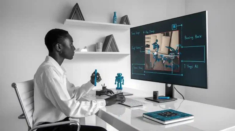
- Integrate AI-powered software for automatic alignment and real-time monitoring.
- Perform regular calibration and maintenance, using advanced techniques like laser interferometry.
- Select compatible positioning equipment that withstands environmental changes.
- Employ robotic or adjustable positioning systems for flexibility in dynamic environments.
- Optimize lighting design and placement to enhance defect visibility at the chosen working distance.
- Use telecentric lenses for precise measurements and minimal distortion when needed.
Mechanical systems with precise motion control help maintain the correct position of cameras and lighting modules. Consistent lighting and programmable controllers support uniform image quality across the inspection area.
Tip: Simulation tools allow engineers to test positioning scenarios before implementation, reducing production disruptions.
Tools and Calculations
Engineers rely on mathematical formulas and specialized software to optimize working distance in a machine vision system. The field of view can be calculated using:
FOV = (Sensor Size × Working Distance) / Focal Length
This formula helps balance the working distance with field of view and magnification, ensuring accurate inspection and quality control. AI-powered software and custom imaging solutions, such as Intelgic’s controllers, assist in optimizing system performance. Vision-based measurement tools now achieve submicron accuracy, outperforming manual methods in both speed and precision. For example, vision systems can measure distances with errors less than 0.15 μm, while manual methods show larger errors and inefficiencies.
Note: Automated tools and calculators simplify the process, making it easier to achieve optimal results in any machine vision system.
Working distance shapes every aspect of a machine vision system, from lens performance to image sensors and camera lens selection. Engineers who measure and optimize working distance achieve sharper focus, better defect detection, and reliable inspections. Stable mounting and precise positioning help maintain accuracy, even in harsh environments. Using tools like calibration targets, telecentric lenses, and manufacturer guidelines supports ongoing improvement. By following best practices and leveraging available resources, teams can maximize the effectiveness of any working distance machine vision system.
FAQ
What is the main purpose of working distance in a machine vision system?
Working distance sets the space between the camera lens and the object. This distance ensures sharp focus and clear images. Engineers use it to match lens performance with inspection needs.
How does working distance affect lens performance and image sensors?
A longer working distance can reduce lens performance and lower the amount of light reaching image sensors. This change may decrease image clarity. Engineers must balance these factors for the best results.
Why is lighting important in machine vision optics?
Lighting helps the system capture clear images. Proper lighting improves contrast and highlights defects. In machine vision optics, engineers adjust lighting to match the working distance and object surface.
Can changing the camera lens improve inspection quality?
Selecting the right camera lens can enhance image quality and detection accuracy. The lens must fit the working distance and field of view. Engineers often test different lenses to find the best match.
What are common mistakes when setting up a working distance machine vision system?
Engineers sometimes ignore space limits or forget to calibrate the system. Poor lighting or the wrong lens choice can also cause problems. Careful planning and testing help avoid these issues.