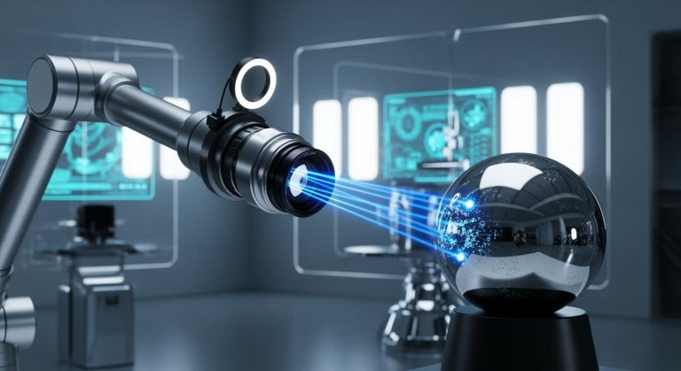
A line light machine vision system uses specialized lighting and cameras to inspect moving objects with high precision. In industrial automation, these systems play a vital role in detecting defects and ensuring product quality. The overall machine vision market, which includes line light machine vision system technology, reached $1.20 billion in 2024 and is expected to grow to $2.50 billion by 2033.
| Metric | Value |
|---|---|
| Market Size (2024) | USD 1.20 Billion |
| Projected Market Size (2033) | USD 2.50 Billion |
| CAGR (2026-2033) | 8.85% |
Lighting directly impacts the accuracy and reliability of machine vision applications. Proper illumination boosts image clarity and contrast, which supports precise inspection. The importance of lighting cannot be overstated for systems that must deliver repeatable results on fast-moving production lines.
Key Takeaways
- Line light machine vision systems use line scan cameras and specialized lighting to inspect fast-moving objects with high accuracy.
- Proper lighting is crucial for clear images, reducing glare and shadows, which improves defect detection and inspection reliability.
- Different lighting techniques like direct, dark field, backlight, and coaxial illumination suit various surfaces and inspection needs.
- Careful setup, including camera alignment and regular calibration, ensures sharp images and consistent inspection results.
- Combining lighting methods and using LED pulse controllers enhances image quality and adapts to diverse industrial applications.
Line Light Machine Vision System
What It Is
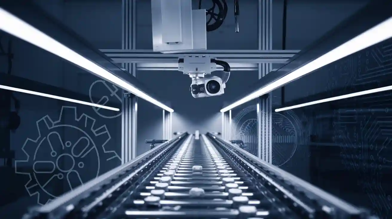
A line light machine vision system is a specialized inspection solution designed for continuous monitoring of moving objects, such as those traveling on conveyor belts. Unlike traditional area scan systems that capture full images in a single shot, this system uses a line scan camera to build images one line at a time. This approach enables high-resolution imaging of large, fast-moving, or cylindrical objects. Line scan cameras excel in applications like web manufacturing, where materials such as fabric, paper, or film move continuously past the inspection point. The system reconstructs a complete image by stitching together thousands of narrow image lines, providing distortion-free and detailed inspection results.
Tip: Think of a line scan camera as working like a scanner or fax machine, capturing data as the object moves past, while an area scan camera works more like a photocopier, taking a snapshot of the whole scene at once.
How It Works
A line scan camera operates using a single row of pixels, known as a linear pixel array. As the object moves perpendicularly to the sensor, the camera captures one line of the image at a time. The system synchronizes this process with the object’s motion, often using rotary encoders to ensure precise alignment. The captured lines are then stitched together by software to form a complete, high-resolution image. This method eliminates motion blur and allows for inspection at very high speeds. Advanced features, such as Time Delay and Integration (TDI), further enhance image quality by increasing light collection without sacrificing speed. Focused illumination from line lights ensures consistent contrast and reduces lighting inconsistencies, which is essential for accurate inspection.
Line scan cameras offer several advantages over area scan cameras in continuous inspection processes:
- They enable distortion-free, high-resolution imaging of moving or cylindrical objects.
- The cameras achieve very high line rates, allowing inspection of products moving at extremely high speeds.
- They provide uniform illumination and exposure control, resulting in superior image quality.
- The system generates less redundant data, which speeds up processing and reduces storage needs.
- Line scan cameras are ideal for inspecting wide or continuous materials, such as paper rolls, textiles, or metal sheets.
Key Components
A line light machine vision system consists of several essential components, each playing a critical role in the inspection process:
| Component | Role |
|---|---|
| Lighting | Provides proper illumination to ensure the camera captures all necessary details; various techniques optimize contrast and image quality. |
| Lens | Focuses light onto the camera sensor, determining image clarity, magnification, and field of view. |
| Camera | Captures images of the object; line scan cameras are used for high-resolution and moving objects. |
| Cabling | Transmits signals between components, ensuring communication and data transfer. |
| Frame Grabber | Converts analog image signals to digital and transmits them to the computer for processing. |
| Software | Processes and analyzes captured images, enabling interpretation and decision-making. |
Line lights provide engineered illumination with precise control over geometry and wavelength, which is crucial for achieving consistent image contrast. LED pulse controllers regulate the current and timing of the lights, enabling high-intensity, short-duration lighting that reduces motion blur and improves image quality. These controllers also help manage thermal effects and ensure the reliability and longevity of the lighting system.
Note: The quality of lighting accounts for up to 80% of the impact on image quality in a line light machine vision system. Proper selection and control of line lights and LED pulse controllers are essential for robust and repeatable inspection results.
Importance in Machine Vision Applications
Image Quality
Proper illumination stands at the core of high-quality imaging in machine vision applications. Lighting, optics, and cameras work together to reveal defects and features that might otherwise remain hidden. When lighting is uniform and well-controlled, images show clear contrast and sharp details. This clarity allows both human inspectors and automated systems to spot even small flaws. Research shows that reflective surfaces and curved shapes often create glare, bright spots, or motion blur. These issues can hide defects and lower inspection reliability. Uniform and diffused lighting arrangements help reduce these problems, making features more visible and images more consistent.
Lighting quality in line light systems affects contrast, glare, and uniformity. Adjusting the angle and intensity of line lights can minimize reflections on shiny surfaces. For example, bar lights angled correctly reduce glare, while ring lights provide even illumination for less reflective objects. Flat-field correction further improves image quality by compensating for uneven lighting and sensor imperfections. This process removes artifacts and ensures every part of the image is clear and usable.
Tip: Consistent, noise-free, and high-resolution images depend on matching lighting methods to the object’s surface and inspection needs.
Inspection Accuracy
Inspection accuracy in machine vision applications improves significantly with optimized lighting setups. Studies have shown that proper lighting can boost inspection accuracy by more than 12%, reaching levels as high as 95%. This improvement comes from better contrast and clearer images, which make it easier for software to detect defects. The spatial arrangement of the object, light source, and camera also plays a key role. Adjusting these elements changes how surface details appear, increasing the reliability of defect detection.
Common challenges include inconsistent illumination, shadows, glare, and reflections. These issues often result from changing ambient light, part orientation, or physical constraints in the inspection area. The table below summarizes some typical challenges and solutions:
| Challenge | Impact | Solution |
|---|---|---|
| Inconsistent Illumination | Missed features, poor contrast | Use stable, even lighting |
| Shadows and Glare | Hidden defects, unreliable results | Apply diffused or backlighting |
| Ambient Light Variability | Flickering, inconsistent images | Use enclosures or high-power strobing |
Understanding the importance of lighting helps engineers design robust systems that deliver reliable results in demanding environments.
Illumination Techniques

Selecting the right illumination technique is essential for achieving reliable inspection results in line light machine vision systems. Engineers must consider object material, surface finish, and inspection goals when choosing among the main types of machine vision lighting. Modern line lights, such as the LCHPX600, LTLNE, and ELINE series, offer high-power LED, oblique, and diffused options to suit a wide range of applications. LED pulse controllers can further boost intensity, making demanding inspections possible without sacrificing image quality.
Direct Lighting
Direct lighting, also known as partial bright field or direct front lighting, shines light onto the object from a slightly off-center angle. This method creates strong contrast and highlights topographic details, making it ideal for surface texture inspection and motion freezing. Engineers often use direct lighting in applications where contrast enhancement is critical. Shadows produced by this technique can help reveal low-contrast features, while ring lights or multiple direct sources can minimize unwanted shadows and glare. Direct lighting is easy to set up and works well for inspecting flat or matte surfaces.
Dark Field
Dark field illumination uses low or medium angle light to highlight surface imperfections and textures. This technique excels at detecting fine defects on reflective or textured surfaces. When light strikes a smooth surface, it reflects away from the camera, resulting in a dark background. Defects scatter the light, making them appear bright against the dark field. This approach increases detection contrast and enables robust inspection of shiny materials like metals, plastics, and glass. Combining dark field illumination with structured diffuse light sources can further improve defect visibility, allowing for accurate detection of scratches, dust, and fingerprints. Engineers often use this method for quality control in industries where surface finish is critical.
Backlight
Backlight illumination places the light source behind the object, creating a high-contrast silhouette. This method is especially useful for detecting holes, gaps, part placement, and performing precise measurements. Backlighting produces sharp edges and clear outlines, which are essential for accurate edge detection. Telecentric backlights, in particular, provide parallel rays that eliminate parallax errors and deliver the highest contrast silhouettes. This setup improves measurement repeatability and defect identification, even at high speeds. Engineers choose backlight illumination for applications that require precise gauging or silhouette imaging, such as inspecting cutouts or verifying part dimensions.
| Backlight Type | Benefits for Edge Detection and Silhouette Imaging | Limitations/Considerations |
|---|---|---|
| Conventional Backlight | Low cost, easy setup, suitable for basic edge detection | High divergence, edge scattering, poor uniformity |
| Masked Backlight | Reduces edge scattering, easy to modify | Does not eliminate scatter completely, needs re-masking |
| Collimated Backlight | Sharper edges, higher uniformity | Higher cost, not truly collimated, may be inefficient |
| Telecentric Illuminator | Highest contrast, sharp edges, ideal for precise measurement | Higher cost, larger size, sensitive alignment |
Coaxial
Coaxial illumination aligns the light source with the camera’s optical path using a beamsplitter. This setup delivers very even and diffuse lighting, which reduces shadows and glare. Coaxial illumination works especially well for inspecting flat, shiny, or specular surfaces, where traditional lighting methods often fail due to reflections. The uniform light reveals surface details that might otherwise be hidden. Engineers sometimes add polarization filters to coaxial setups to further reduce specular reflections, though this can decrease overall light intensity. Flat dome lights, which mimic coaxial illumination, also help minimize reflections and glare, providing clear images of reflective objects.
| Illumination Technique | Working Principle | Advantages |
|---|---|---|
| In-line (Coaxial) | Light source integrated via beamsplitter; specular reflections return to lens | Compact design, ideal for specular objects, even illumination |
| Diffuse Axial Illumination | Diffuse light introduced coaxially; combines bright and dark field angles | Very even illumination, reduces glare, avoids hot spots |
| Telecentric Illumination | Collimated backlighting with parallel rays | High edge contrast, accurate measurement, repeatability |
Combining Methods
Combining multiple illumination techniques in a single setup can significantly improve inspection reliability. For example, using both bright field and dark field illumination reveals features that remain hidden with only one method. This approach reduces glare and enhances image clarity, especially on reflective or complex surfaces. Engineers can tailor lighting to handle diverse surface types, such as flat, matte, reflective, or curved objects. Computational imaging, which merges images captured under different lighting conditions, further increases contrast and reveals subtle features. Adjusting lighting wavelength and ambient light in combination with these methods enhances inspection accuracy and reliability.
Tip: Combining line lights with advanced LED pulse controllers allows for flexible, high-intensity illumination that adapts to changing inspection needs. This flexibility ensures optimal results across a wide range of industrial applications.
Line Scan Camera Setup
Choosing Lighting
Selecting the right lighting for a line scan camera setup shapes the success of any surface inspection. Engineers must match the lighting method to the application type. Flat, shiny, or transparent surfaces each need a different approach. For example, backlighting works well for silhouettes, while dome lighting reduces reflections on curved parts. The angle and placement of the light affect how defects appear. Low-angle lights highlight scratches, and coaxial lights suit flat, reflective surfaces. The color of the light also matters. Red light is a good general choice, blue or green can reveal fine details, and infrared or ultraviolet light helps with special tasks. Brightness and stability ensure the camera captures clear images every time. The form factor, such as bar, ring, or line light, must fit the inspection area. Engineers often choose between integrated lights for compact setups or a separate lighting setup for more flexibility.
Tip: Address lighting optimization early in the design process to avoid costly changes later.
Alignment Tips
Proper alignment of line scan cameras and lights ensures full coverage and accurate inspection. Engineers should position the camera to cover the entire width of the object. Sometimes, multiple cameras are needed for wide materials. The table below shows best practices for alignment:
| Best Practice Aspect | Description |
|---|---|
| Proper Lighting | Use diffuse or polarized lighting to reduce glare and improve defect detection. |
| Camera Placement | Place cameras at angles that cover the whole inspection area. |
| Sensor Calibration | Calibrate sensors regularly to avoid missed defects. |
| Real-Time Feedback | Use monitoring systems for immediate alerts about defects. |
| Integration with Automation | Connect inspection systems to production lines for better control. |
Engineers should also consider physical space and avoid obstructions that block the camera or light. Modular systems make installation easier and allow for quick adjustments.
Calibration
Calibration keeps the line scan camera system accurate and reliable. Engineers must synchronize the camera’s line rate with the speed of the moving object. This prevents motion blur and timing errors. Two main methods exist: time-based synchronization for steady conveyor speeds and distance-based synchronization using encoders. Regular calibration avoids image distortion and ensures sharp, clear images. Consistent LED lighting also helps maintain even image quality. Staff training and routine checks reduce downtime and prevent costly mistakes.
Note: Combining line scan cameras with the right lighting setup delivers the best results for industrial inspection, especially in high-speed environments.
- Line light machine vision systems deliver high-speed, precise, and reliable automated inspection across many industries.
- Line scan cameras and bar lighting enable continuous, high-contrast imaging, reducing human error and increasing throughput.
- Proper illumination and thoughtful setup ensure accurate, repeatable results for defect detection, measurement, and classification.
- Industry experts, such as those at the Association for Advancing Automation, and resources like Quality Magazine and Smart Vision Lights, offer valuable guidance for tailored solutions.
For those seeking to implement or optimize these systems, consulting with experienced professionals can maximize inspection performance.
FAQ
What industries use line light machine vision systems?
Manufacturers in electronics, automotive, packaging, textiles, and food processing use these systems. They help inspect moving products for defects, measure dimensions, and ensure quality. Any industry with continuous production lines can benefit from this technology.
How do line lights differ from area lights?
Line lights focus illumination in a narrow strip, matching the camera’s line sensor. Area lights spread light over a wide region. Line lights provide higher contrast and detail for moving objects, while area lights suit static or slow-moving inspections.
Can line light systems inspect transparent or reflective materials?
Yes. Engineers use specialized lighting techniques, such as backlighting or coaxial illumination, to inspect glass, plastics, or shiny metals. These methods reduce glare and highlight edges or defects, making inspection of challenging surfaces possible.
How often should engineers calibrate a line scan camera system?
Engineers should calibrate systems during installation and after any major changes. Regular checks, such as monthly or quarterly, help maintain accuracy. Frequent calibration ensures reliable results and reduces the risk of missed defects.
See Also
Understanding Semiconductor Vision Systems In Machine Technology
How To Properly Position Equipment For Machine Vision
Complete Insights Into Machine Vision For Industrial Automation
Exploring The Role Of Cameras Within Vision Systems
The Impact Of Structured Light On Machine Vision Performance