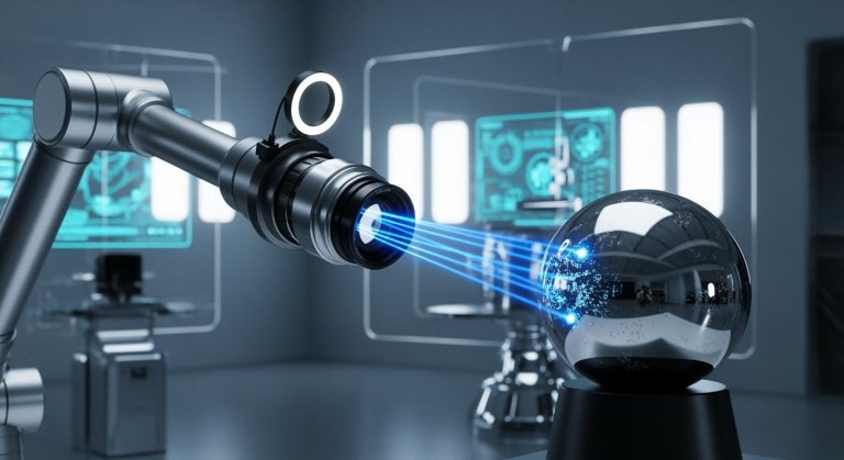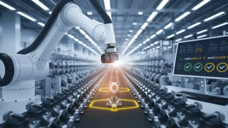
Focal distance plays a critical role in determining image quality in any machine vision system. When a camera in a factory inspects products, the wrong focal distance can create blurry images, limit the field of view, or miss tiny defects. Camera placement, lighting, and lens choice all influence how systems capture details. If lighting reflects poorly or the camera sits too far, systems may fail to detect flaws. Proper focal distance machine vision system design helps cameras work with lighting and systems to deliver sharp results.
Key Takeaways
- Focal distance controls image sharpness, field of view, and magnification, making it vital for clear machine vision inspection.
- Focal length is a lens property that affects zoom and view size; working distance is the real gap between camera and object.
- Choosing the right lens means balancing field of view, magnification, depth of field, and lighting to fit the inspection task.
- Always match the lens to the camera sensor size and plan working distance carefully to avoid blurry images or missed details.
- Test the full system with real objects and lighting before finalizing to ensure reliable, sharp image capture and defect detection.
Focal Distance Basics
What Is Focal Distance?
Focal distance describes how a lens focuses light to form a sharp image on the image sensor. In a machine vision system, this measurement determines how the camera captures details from the scene. Engineers use focal length, measured in millimeters, to select the right lens for each application. The focal length affects the field of view and magnification. Shorter focal lengths give a wider field of view, while longer focal lengths provide higher magnification and a narrower view.
The technical definitions of focal distance help clarify its role in optical systems. The table below summarizes key terms:
| Term | Definition |
|---|---|
| Effective Focal Length | Distance from the optical center to the focus when parallel light enters the system. |
| Front Focal Length | Distance from the front principal plane to the front focal point. |
| Rear Focal Length | Distance from the rear principal plane to the rear focal point. |
| Front Focal Distance | Distance from the front focal point to the first optical surface. |
| Back Focal Distance | Distance from the last optical surface to the rear focal point. |
A machine vision system designer must understand these terms to choose the right lens for the camera and image sensor. The correct focal distance machine vision system setup ensures the camera captures sharp images, even in challenging lighting conditions.
Focal Distance vs. Working Distance
Focal length and working distance are not the same. Focal length is an intrinsic property of the lens. It defines how the lens bends light and forms an image. Working distance, on the other hand, is the real-world distance from the front of the lens to the object being inspected. In machine vision, both measurements use millimeters.
For a single lens, the working distance can match the focal length. In complex lenses, such as those in an industrial camera, the working distance often becomes shorter than the focal length. This difference matters in machine vision because the working distance tells the engineer how close the camera must be to the object for a sharp image. The focal length, however, controls the field of view and magnification.
Lighting also plays a role. The camera, lighting, and lens must work together. If the working distance is too short, lighting may not reach the object evenly. If the focal length is too long, the camera may miss important details outside the field of view. In every machine vision system, balancing focal length, working distance, and lighting ensures the camera and image sensor deliver clear, useful images for inspection.
Key Parameters in Machine Vision
Field of View
Field of view describes how much of a scene the camera can see at once. In a machine vision system, focal length directly controls the angular field of view. A shorter focal length, such as 8 mm, allows the lens to capture a wider area. This wide field of view helps when inspecting large objects or scanning broad conveyor belts. A longer focal length, like 50 mm, narrows the field of view and focuses on a smaller region. This setup works best for detailed inspections where the camera must find tiny defects. The combination of focal length and image sensor size sets the total field of view. Engineers must match the lens to the application to avoid missing important details or introducing distortion at the edges.
Magnification
Magnification measures how much larger or smaller the camera makes the object appear on the image sensor. Changing the focal length or adjusting the working distance changes magnification. For example, adding a spacer to a 35 mm lens increases the image distance and reduces the working distance, which more than doubles the magnification. The thin lens formula, 1/f = 1/o + 1/i, and the magnification formula, M = -i/o, show how these variables interact. In industrial camera setups, higher magnification helps capture fine details but may require the camera to move closer to the object. Selecting the right focal length ensures the camera delivers the needed magnification for accurate image processing.
| Focal Length | Field of View | Magnification | Typical Use Case |
|---|---|---|---|
| 8 mm | Wide | Low | Large object inspection |
| 16 mm | Moderate | Medium | General-purpose machine vision |
| 25 mm | Narrow | High | Small part inspection |
| 50 mm | Very Narrow | Very High | Micro-defect detection |
Resolution and Depth of Field
Resolution defines how clearly the camera can capture small features. Depth of field describes how much of the scene stays in focus at once. Focal distance machine vision system design must balance these two factors. A smaller aperture increases depth of field, keeping more of the object sharp, but can reduce resolution due to diffraction. Higher magnification, often achieved with longer focal lengths, can make these effects stronger. The camera, lighting, and lens must work together to achieve the right balance. For example, focusing at the hyperfocal distance maximizes depth of field, which is useful for inspecting objects at different heights. However, this may require adjustments in lighting or image sensor settings to maintain image quality. Engineers use depth of field calculators to find the best settings for each application, ensuring the camera captures sharp images for reliable image capture and processing.
Focal Distance Machine Vision System Selection
Lens Selection Guide
Selecting the right lens for a focal distance machine vision system requires a structured approach. Engineers must consider several factors to ensure the camera captures sharp, accurate images for reliable image processing. The following steps outline a proven method:
-
Define the Working Distance and Field of View
The working distance is the space between the lens and the object. The field of view describes the area the camera must capture. Engineers measure the object size and decide how much of it should appear in the image. -
Specify Sensor Size and Resolution
The sensor size affects the field of view and compatibility with the lens. Matching the lens to the sensor prevents vignetting and distortion. The required resolution depends on the smallest feature the camera must detect. -
Calculate the Required Focal Length
Use the object size, working distance, and sensor size to determine the focal length. This calculation ensures the camera frames the object correctly. -
Estimate Depth of Field
The depth of field is the range where the object appears sharp. Engineers adjust the aperture and focal length to balance sharpness and brightness. Smaller apertures increase depth but may require more lighting. -
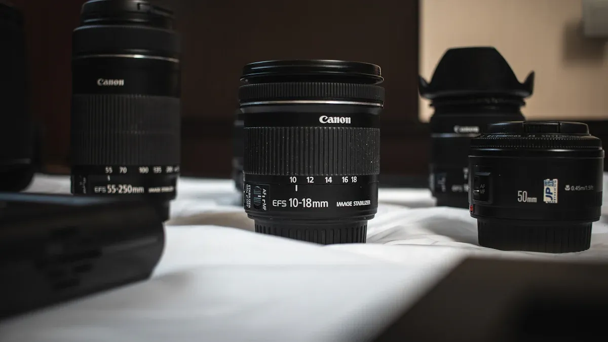
Select Lens Type
Fixed focal length lenses provide stable performance and high image quality. Zoom lenses offer flexibility but may reduce resolution. Telecentric lenses help when precise measurements are needed. -
Check Mechanical and Environmental Constraints
The camera and lens must fit within the available space. Engineers consider lighting, vibration, and temperature to ensure reliable operation.
Tip: Always match the lens to the sensor size and application needs. Avoid using a lens with a smaller image circle than the sensor, as this causes vignetting.
Practical Formulas
Engineers use several formulas to calculate the best focal length and working distance for a focal distance machine vision system. These formulas help balance field of view, magnification, and image quality.
-
Focal Length Calculation:
Focal Length (mm) = (Sensor Size × Working Distance) / Field of ViewThis formula helps select a lens that fits the object within the camera’s view.
-
Angular Field of View (AFOV):
AFOV = 2 × arctan (Sensor Dimension / (2 × Focal Length))Use this to determine how much of the scene the camera can see.
-
Magnification:
Magnification = Focal Length / Working DistanceThis shows how large the object appears on the sensor.
-
Thin Lens Equation:
1/s1 + 1/s2 = 1/fWhere s1 is the object distance (working distance), s2 is the image distance, and f is the focal length.
| Parameter | Formula Example | Description |
|---|---|---|
| Focal Length | (Sensor Size × WD) / FOV | Calculates lens focal length |
| AFOV | 2 × arctan (Sensor Dim / (2 × Focal Length)) | Finds angular field of view |
| Magnification | Focal Length / Working Distance | Determines object size on sensor |
| Thin Lens Eq. | 1/s1 + 1/s2 = 1/f | Relates object, image, and focal distances |
Note: Always use consistent units (millimeters) for all measurements.
Application Examples
Engineers apply these formulas and guidelines to real-world focal distance machine vision system design. The following examples show how to balance field of view, working distance, and lighting for different tasks:
-
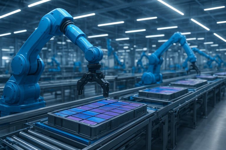
Large Object Inspection on a Conveyor
An industrial camera must inspect boxes moving on a conveyor. The engineer measures the box size and sets the working distance based on available space. Using the sensor size and desired field of view, the engineer calculates the focal length. A short focal length lens provides a wide field of view, allowing the camera to capture the entire box. Bright, even lighting ensures the camera detects surface defects. -
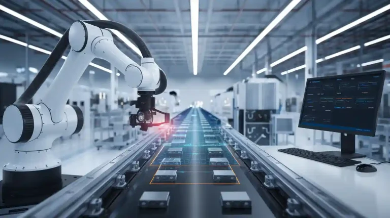
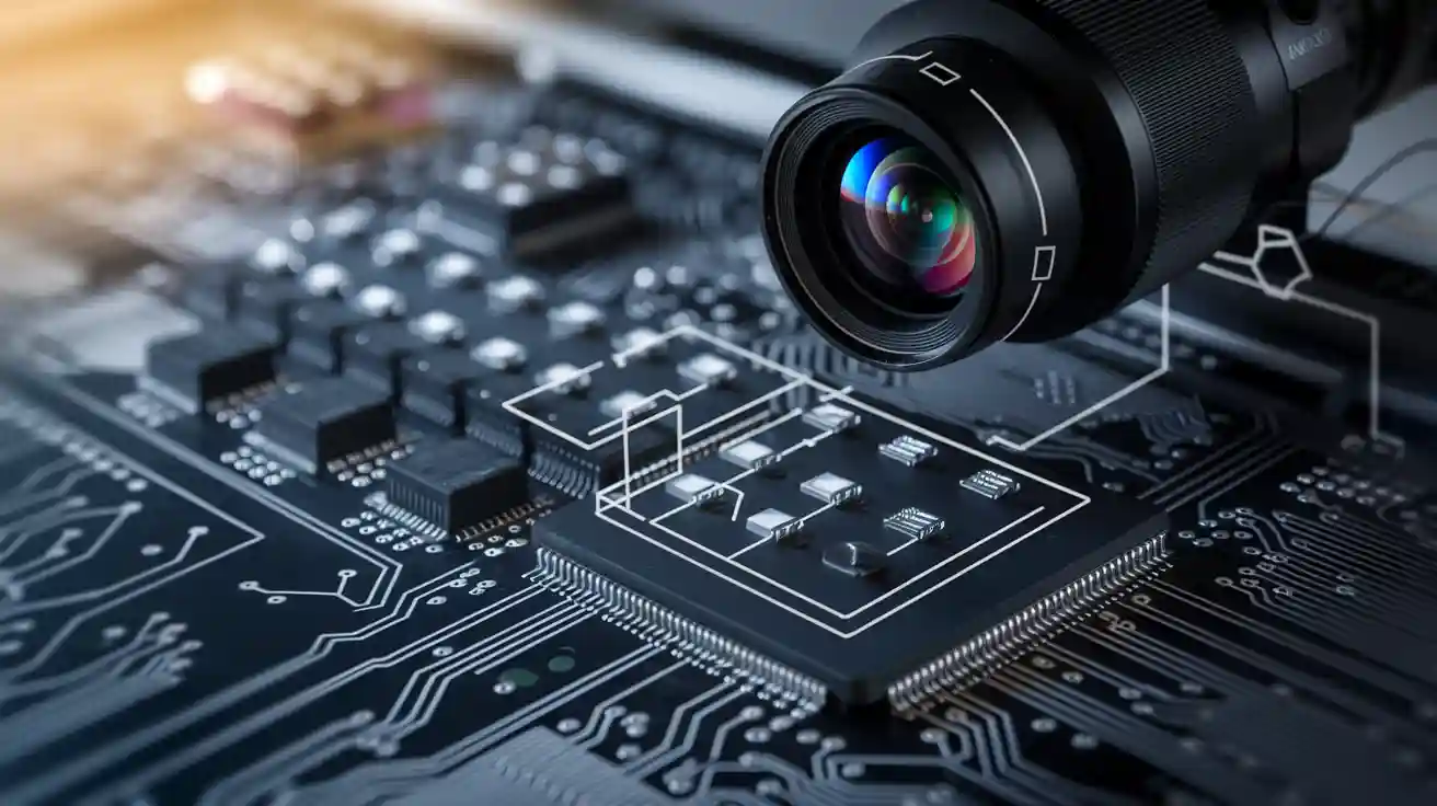
Micro-Defect Detection in Electronics
For inspecting tiny solder joints, the engineer selects a longer focal length lens for higher magnification. The working distance becomes shorter, so the camera must move closer to the object. The engineer uses a small aperture to increase depth of field, but adds extra lighting to maintain image brightness. This setup allows the camera to reveal small defects that could cause product failures. -
Barcode Reading in High-Speed Sorting
A camera reads barcodes on fast-moving packages. The engineer chooses a lens with a focal length that matches the sensor size and working distance, ensuring the barcode fills most of the field of view. Strong, focused lighting helps the camera capture sharp images at high speeds, improving image processing accuracy.
Tip: Always test the system with real objects and lighting before finalizing the lens choice. Adjust focal length or working distance if the camera misses details or the image appears blurry.
Engineers must balance several trade-offs in focal distance machine vision system design. Shorter focal lengths increase field of view but can introduce distortion and reduce magnification. Longer focal lengths improve detail but narrow the field of view and may require more lighting. The right choice depends on the application, available space, and inspection requirements. Careful planning and testing help systems deliver reliable results.
Common Pitfalls
Overlooking Requirements
Many engineers make mistakes by not fully understanding the needs of the inspection task. They may forget to consider the size of the object, the smallest feature to detect, or the space available for the camera and lens. Some skip checking if the lens matches the sensor size or if the system can handle the required resolution. Others ignore the importance of depth of field or do not plan for the right working distance. These oversights can lead to blurry images, missed defects, or even the need to redesign the system.
Tip: Always list out all requirements before choosing a lens. Include object size, working distance, sensor size, and lighting needs. This helps avoid costly mistakes.
Common mistakes include:
- Not saving enough space for the camera and lens, causing installation problems.
- Failing to balance working distance and field of view, which can make it hard to get sharp images.
- Overlooking the effect of lighting on image quality.
- Ignoring the need for special lenses, such as telecentric lenses, when precise measurements are required.
Misreading Lens Specs
Engineers often misinterpret lens specifications. This happens when they confuse terms like working distance and field of view or do not understand how sensor size affects lens choice. The table below shows some common issues and their outcomes:
| Parameter | Misinterpretation Issue | Consequences |
|---|---|---|
| Working Distance | Confused with field of view | Poor resolution, installation challenges |
| Sensor Size | Changed late in design | Redesign, higher costs |
| Field of View | Wide angles not balanced with working distance | Distortion, loss of detail |
| Resolution | Tradeoffs with distortion not understood | Suboptimal image quality |
Designers sometimes believe that telecentric lenses always provide a larger depth of field. In reality, depth of field depends on the aperture and resolution, not the lens type. Misreading these specs can result in systems that do not meet performance goals.
Ignoring Integration
Successful systems require careful integration of all parts. The camera, lens, sensor, and lighting must work together. If one part does not fit, the whole system can fail. Some engineers forget to check if the lens and camera interface are compatible. Others do not consider how lighting will affect the image or if the lens can handle the required field of view at the set distance.
Note: Always test the complete system with real objects and lighting before finalizing the design. Adjust the camera or lighting if the image is not clear.
Best practices include:
- Matching the lens to the sensor size and resolution.
- Maintaining the correct working distance for the lens.
- Considering the depth of field around the working distance.
- Planning for lighting that matches the inspection task.
Ignoring these steps can lead to poor image quality, missed defects, or costly redesigns. Careful planning and testing help ensure the system works as intended.
Focal distance shapes how a camera captures detail, balances field of view, and supports reliable systems. Proper selection ensures the camera delivers sharp images, even when lighting changes or object sizes vary.
- Correct focal distance balances magnification and field of view, improving detection and repeatability.
- Engineers should:
- Identify field of view, resolution, working distance, and depth of field.
- Match lens and lighting to application needs.
- Use online calculators and technical support for lens selection.
Advancements in lens technology and lighting now allow systems to adapt quickly, supporting future inspection needs.
FAQ
What is the difference between focal length and working distance?
Focal length describes the lens’s optical property. Working distance measures the space from the lens to the object. Engineers use focal length to set magnification and field of view. Working distance helps determine camera placement.
How does focal distance affect image quality in machine vision?
Focal distance controls how much detail the camera captures. A correct focal distance produces sharp images. An incorrect focal distance can cause blurriness or miss small defects. Engineers select focal distance based on inspection needs.
Can one lens work for every machine vision application?
No single lens fits all tasks. Each application needs a lens matched to object size, required detail, and available space. Engineers often test several lenses to find the best fit for each project.
What happens if the lens does not match the sensor size?
| Issue | Result |
|---|---|
| Vignetting | Dark corners in image |
| Cropping | Lost image area |
| Distortion | Blurred or warped view |
A mismatched lens and sensor can reduce image quality and inspection accuracy.
See Also
A Comprehensive Guide To Dimensional Measurement In Vision Systems
Exploring The Fundamentals Of Camera Resolution In Vision Systems
The Importance Of Field Of View In Vision Systems 2025
An Overview Of Cameras Used In Machine Vision Systems
Understanding Lenses And Their Role In Machine Vision Systems