Distortion in a distortion machine vision system often leads to errors in measurement and object alignment. Recent trends in 2025 show that advanced calibration techniques, real-time feedback tools, and AI-powered solutions now help correct lens distortion more effectively.
- Automated alignment, sub-pixel algorithms, and robust hardware like telecentric lens options improve both accuracy and reliability.
- Software solutions use distortion correction algorithms to restore image geometry, while hardware advances such as ultra-low distortion lens designs minimize errors at the source.
A distortion machine vision system that uses these solutions will see fewer measurement errors and higher repeatability. By managing distortion, every system can achieve more reliable results.
Key Takeaways
- Distortion in machine vision systems causes image errors that affect measurement accuracy and object detection.
- Different types of distortion, like barrel and pincushion, change how images look and must be corrected for reliable results.
- Regular calibration and choosing the right lenses, especially ultra-low distortion or telecentric lenses, improve measurement precision.
- AI-powered real-time correction tools help detect and fix distortions quickly, boosting system speed and accuracy.
- Combining hardware and software solutions offers the best balance of performance, flexibility, and reliability in distortion correction.
Distortion Machine Vision System
What Is Distortion?
Distortion in a distortion machine vision system changes how an image appears. It happens when the magnification in an image varies across the field of view at a fixed working distance. This effect comes from the optical design of the lens. Unlike parallax, which changes with distance, distortion stays the same at a set distance. Distortion does not remove image content but moves it to the wrong place. This makes straight lines look curved or objects appear stretched or squished. Engineers call this a third-order aberration. The amount of distortion depends on the lens, its focal length, and the size of the field of view. Barrel distortion makes points look closer to the center, while pincushion distortion pushes them outward. These changes can be measured as a percentage of the field height.
Tip: Understanding distortion helps engineers choose the right lens for image acquisition and detection tasks.
The table below lists common causes of distortion in a distortion machine vision system:
| Cause of Distortion | Description | Effect/Notes |
|---|---|---|
| Optical design of lenses | Magnification changes across the field of view. | Critical for precision; varies with wavelength and distance. |
| Field of View (FOV) size | Larger FOVs increase distortion. | Wide FOVs are more prone to distortion. |
| Focal length | Shorter focal lengths increase distortion. | Trade-off between wide FOV and distortion. |
| Lens design complexity | More elements or special glass can reduce distortion. | May lower resolution. |
| Telecentric lenses | Usually have little distortion. | Best for minimal distortion needs. |
Why It Matters
Distortion affects every part of a distortion machine vision system. Even small amounts of lens distortion can cause big problems in measurement and detection. For example, barrel distortion makes straight lines curve outward, which can make objects look larger than they are. Pincushion distortion bends lines inward, leading to overestimated measurements. These errors can cause production mistakes, missed defects, and system downtime.
Distortion also impacts image acquisition. Poor lens selection can lead to blurry images and focus issues. This reduces the accuracy of detection and measurement. Environmental factors, like temperature changes or vibration, can shift lens parts and increase distortion. Ruggedized lenses help keep measurements accurate in tough conditions.
A distortion machine vision system must use regular calibration and proper lens selection to keep measurements reliable. Modern system architectures, such as encoder-decoder models, help correct complex distortions. These models learn how to fix errors from different types of lens distortion, improving both detection and real-time correction.
Types of Lens Distortion
Radial and Tangential Distortion
Radial and tangential distortion are the two main ways a lens can change how an image looks. Radial distortion happens because of the shape and design of the lens. It causes straight lines to curve either outward or inward from the center of the image. This effect is common in many machine vision systems and can make measurements less accurate. Tangential distortion, on the other hand, comes from a misalignment between the lens and the camera sensor. When the lens is not perfectly centered or tilted, it bends lines in an uneven way. This type of distortion often appears as lines that curve more on one side of the image than the other.
Both radial and tangential distortion can make it hard for a machine vision system to detect features or measure objects correctly. Engineers use calibration methods to estimate how much distortion is present and then apply corrections. These corrections help restore the true shape of objects in the image.
Note: Radial distortion affects the whole image in a circular pattern, while tangential distortion causes uneven bending due to lens misalignment.
Barrel, Pincushion, Mustache, Keystone
Different types of lens distortion create unique effects in images. The table below shows the most common types found in machine vision systems:
| Distortion Type | Description | Typical Lens or Cause |
|---|---|---|
| Barrel distortion | Straight lines curve outward, making the image look like a barrel. | Wide-angle lens |
| Pincushion distortion | Straight lines bend inward, similar to the shape of a pincushion. | Telephoto lens |
| Mustache distortion | A mix of barrel and pincushion effects, causing wave-like curves in lines. | Complex wide-angle lens designs |
| Keystone distortion | Vertical lines converge or diverge, creating a trapezoid shape when the camera is tilted. | Camera not parallel to subject |
Barrel distortion often appears in wide-angle lenses. It makes objects near the edge of the image look stretched. Pincushion distortion is common in telephoto lenses and causes the edges to pinch inward. Mustache distortion combines both effects, creating a wavy pattern that can be hard to correct. Keystone distortion does not come from the lens itself but from the camera angle. When the sensor is not parallel to the object, vertical lines tilt, and the image looks like a trapezoid.
Machine vision systems must handle these types of lens distortion to keep measurements accurate. Each type can disrupt spatial relationships and make it harder to analyze images. Regular calibration and careful lens selection help reduce these problems.
Impact on Accuracy
Measurement Errors
Distortion changes the way a camera captures objects, which can lead to measurement errors. When a lens bends straight lines or shifts object positions, the measurements taken from these images become less reliable. Studies using digital image correlation show that distortion introduces errors in displacement and strain measurements. By applying advanced correction methods, such as piecewise spline functions on the pixel plane, these errors can be removed. This approach works well, especially for areas far from the center of the image, where distortion is often strongest.
A 2D camera imaging model shows that distortion, as part of the camera’s internal settings, has a big effect on measurement accuracy. Experiments with industrial and telecentric lenses confirm that reducing radial distortion improves precision. If the measurement plane does not match the calibration plane, the errors become even larger. Choosing lenses with low distortion, like telecentric lenses, helps keep measurements sharp and accurate. This is important for tasks that require high image quality and precise object reproduction.
Measurement errors caused by distortion also affect quality control in automated inspection. For example, in medical needle manufacturing, distorted images can lead to mistakes in defect detection and product classification. Automated systems may misjudge which products meet quality standards if distortion is not corrected.
Edge Effects
Distortion often causes the most visible problems at the edges of an image. Fish-eye lenses, for example, create curved lines and stretch objects near the borders. This stretching changes how people and machines judge speed, distance, and size. Objects at the edge may look larger or move faster than they really do. These edge effects make it hard to measure objects or understand their true position in the scene.
- Common edge effects from distortion:
- Curved lines and stretched shapes near the image border
- Overestimation of object size at the edges
- Confusion in spatial layout and navigation tasks
Distortion at the edges also causes problems when stitching images together to make panoramas. Without correction, the images do not line up, and the final panorama looks mismatched. Advanced algorithms are needed to fix these issues and keep the stitched image quality high.
Lens Distortion Correction

Calibration Methods
Calibrating distortion in machine vision systems ensures accurate measurements and reliable image analysis. Most calibration methods treat lens distortion as a fixed system error for each camera and lens setup. Engineers often use a linear camera model and focus on feature points near the image center to calibrate the perspective projection. This approach simplifies lens distortion correction, especially for 2D measurements. Smoothing spline functions can correct distortion in a specific region of interest on the pixel plane. After applying these corrections, measurement accuracy improves, which is vital for precision tasks.
A popular calibration technique involves capturing multiple images of a calibration target, such as a checkerboard or dot grid, from different angles. Calibration software detects pattern points and estimates both intrinsic parameters (like focal length and principal point) and extrinsic parameters (such as camera position). The software then calculates lens distortion coefficients for radial and tangential distortions. This process corrects common issues like barrel, pincushion, and mustache distortion. Zhang’s flexible method, which uses planar 2D targets, and line-based calibration methods are widely used. Some advanced methods allow calibration from a single image using non-linear optimization to estimate radial distortion coefficients. Tools like OpenCV and MATLAB help detect calibration patterns and compute parameters.
Tip: For best results, engineers should use at least 10–15 images with clear pattern visibility and good lighting. Sub-pixel corner detection increases calibration accuracy.
The table below compares the accuracy and complexity of different calibration methods:
| Calibration Method | Accuracy Impact | Complexity | Notes |
|---|---|---|---|
| Temperature Scaling (TS) | High accuracy for current models | Simple, low computational cost | Works well for many vision systems |
| Ensemble Temperature Scaling (ETS) | Slight improvement over TS | More complex | Higher computational cost, limited extra benefit |
| Isotonic Regression (IRM) | Superior calibration in natural images | More complex, accuracy-preserving | Best for high-quality calibration |
| Spline Calibration (SPL) | Similar to IRM, high accuracy | More complex | Effective for natural image datasets |
Post-hoc calibration methods like TS, ETS, IRM, and SPL perform well when the system operates under normal conditions. However, their performance drops if the environment changes a lot. The choice of calibration method depends on the model, dataset, and application needs.
Recent case studies show that advanced distortion correction techniques work well in real-world applications. For example, in medical imaging, researchers used both field map-based and field map-less methods to correct distortion in MRI scans. These solutions improved image quality and reliability, even with different scanning protocols. In microscopy, computer vision-based distortion correction allowed scientists to track tiny changes in materials at the nanoscale. Corrected images aligned closely, making precise measurements possible.
Hardware vs. Software
Engineers can choose between hardware-based and software-based approaches for lens distortion correction. Each solution has its own strengths and weaknesses.
| Aspect | Hardware-Based Approaches | Software-Based Approaches |
|---|---|---|
| Performance | High, real-time processing (20+ fps, low latency) | Lower, may not handle complex tasks in real time |
| Latency | Low, ideal for robotics and autonomous systems | Higher, less suited for time-critical applications |
| Scalability | Scalable with parallel hardware cores | Limited by CPU core count |
| Development Complexity | High, needs specialized skills | Lower, easier to program and update |
| Flexibility | Low, hardware changes are costly | High, software updates are simple |
| Use Cases | Robotics, autonomous vehicles, embedded systems | Prototyping, less demanding applications |
Hardware-based lens distortion correction uses devices like FPGAs or hardware accelerators. These systems deliver high computational power and low latency, which is important for real-time control in robotics or autonomous vehicles. However, developing hardware solutions takes more time and requires special skills. Changing hardware is also expensive.
Software-based correction runs on multicore CPUs or GPUs. This approach offers flexibility and is easier to update or modify. Software can model complex distortions and adapt to new requirements. However, it may not meet real-time demands for complex corrections. Machine learning-based software solutions need large datasets and significant computing resources for training.
Some systems use a hybrid approach, combining hardware and software. This method leverages the speed of hardware and the flexibility of software. Real-time lens distortion correction becomes possible with specialized hardware or optimized software. In practice, hardware-based solutions are preferred for applications that need low latency and high throughput, while software-based solutions suit prototyping and less demanding tasks.
Note: Choosing the right distortion correction solution depends on the application’s speed, accuracy, and flexibility requirements.
Image Processing Trends 2025
AI and Real-Time Correction
Artificial intelligence has changed how engineers approach image processing in machine vision. In 2025, deep learning models such as convolutional neural networks (CNNs), recurrent neural networks (RNNs), and generative adversarial networks (GANs) play a major role in distortion correction. These models analyze images, detect distortions, and apply corrections automatically. They help systems achieve high accuracy and speed, even in challenging environments.
AI-powered tools like StarXTerminator and BlurXTerminator use deep learning to detect and isolate features, restore fine details, and correct distortions without adding noise. NoiseXTerminator applies selective noise reduction, keeping important structures clear. These tools improve image quality by correcting issues caused by optical imperfections or environmental factors.
Modern frameworks such as DeepClean automate real-time processing. They identify the type of distortion in each image and select the best correction algorithm instantly. This dynamic approach allows machine vision systems to adapt to new types of distortion without manual setup. Real-time processing ensures that systems can inspect hundreds or thousands of parts per minute, matching the speed of production lines.
AI-driven calibration methods also automate the estimation of camera parameters. These methods correct lens distortions like barrel, pincushion, and mustache effects. By analyzing images of reference patterns, AI reduces manual work and increases calibration accuracy. This automation benefits industries such as robotics, autonomous vehicles, and medical imaging.
Some of the latest advancements in AI-powered image processing for distortion correction include:
- Deep learning models that restore fine details and correct distortions in real time.
- Automated detection and correction of multiple distortion types in a single processing step.
- Real-time field mapping for dynamic correction during changing conditions.
- AI-driven calibration that improves accuracy and reduces manual intervention.
Industrial machine vision systems now use AI to achieve defect detection rates above 99%. These systems inspect thousands of parts per minute and maintain consistent performance. They also reduce costs by lowering warranty claims and improving predictive quality management. Metrics such as mean squared error (MSE), peak signal-to-noise ratio (PSNR), and structural similarity index (SSIM) help engineers measure the effectiveness of these solutions.
Tip: AI-powered real-time processing not only improves accuracy but also adapts to new challenges, making it a reliable distortion correction solution for modern factories.
Ultra-Low Distortion Lenses
Ultra-low distortion lenses have become essential for high resolution and precise measurement in machine vision. Manufacturers design these lenses to minimize image warping, ensuring that straight lines remain straight and measurements stay accurate. In 2025, new models offer features that support demanding inspection tasks.
Key features of ultra-low distortion lenses include:
- 6 Megapixel resolution optimized for 2/3" sensors.
- Fixed focal lengths from 5mm to 75mm.
- Distortion reduced to 0.01% or less, critical for high-precision applications.
- Compact, lightweight C-mount design for easy integration.
- Ensured corner brightness for uniform image quality.
- Short working distances for flexible inspection setups.
- Compatibility with multiple sensor types, including IMX250 and IMX264.
- Floating mechanisms that maintain optical performance across different distances.
- Improved contrast for clear detection of low-contrast targets.
- Environmentally resistant models with IP64 rating for harsh factory conditions.
| Feature | Benefit |
|---|---|
| Ultra-low distortion (<0.01%) | Accurate measurements, minimal image warping |
| High resolution (6MP) | Detailed image capture |
| Floating mechanism | Consistent performance at all distances |
| Environmental resistance | Reliable in tough industrial settings |
| Focus locking mechanism | Stable and easy focus adjustment |
Telecentric lenses, a type of ultra-low distortion lens, offer unique advantages. They produce images with almost no distortion or blurring. Their parallel light ray design eliminates off-axis aberrations, which leads to sharper images and higher measurement accuracy. These lenses keep image size consistent, even when object distance changes, and provide a high depth of field.
Scientific studies show that combining ultra-low distortion lenses with digital image processing methods such as Digital Image Correlation (DIC) achieves correction accuracy within 0.02 pixels. This performance far exceeds traditional correction methods, which often have errors of 1-2 pixels. The result is better measurement accuracy and improved system performance.
Manufacturers now integrate these lenses into commercial machine vision products. They also use advanced calibration routines and error detection algorithms to maintain accuracy over time. Regular recalibration, especially after moving the system, helps ensure reliable results.
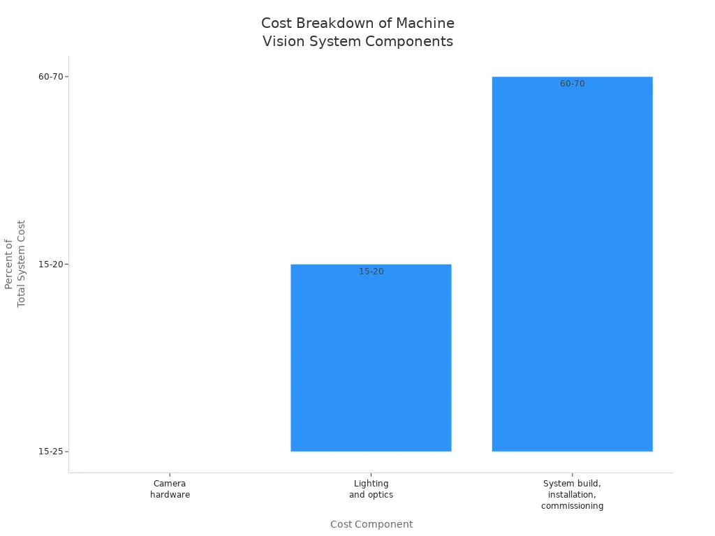
Cost remains an important factor when choosing ultra-low distortion lenses. Standard lenses cost less and offer more flexibility but require frequent calibration and maintenance. Ultra-low distortion lenses, such as telecentric models, cost more upfront and are larger, but they provide consistent calibration and higher accuracy. Over time, these lenses reduce downtime and improve inspection accuracy, balancing the higher initial investment with long-term benefits.
Note: Investing in high-quality lenses and advanced digital image processing tools leads to better measurement accuracy, fewer errors, and more reliable automated inspection.
Recent trends show that rigorous calibration, AI-driven algorithms, and advanced software now lead distortion correction. Understanding barrel, pincushion, and mustache distortion helps engineers select the right lens and correction method. Experts recommend using vendor-specific algorithms, validating corrections, and fine-tuning settings for best results. For up-to-date information, OEVIS® by Opto Engineering provides advanced resources and calibration tools.
FAQ
What is the main cause of distortion in machine vision systems?
Lens design often causes distortion. The shape and arrangement of lens elements change how light bends. This effect shifts straight lines and alters object shapes in images. Engineers select special lenses or use calibration to reduce distortion.
How does distortion affect measurement accuracy?
Distortion changes the position and size of objects in images. This leads to errors in measuring length, width, or angles. Accurate measurements require correction methods that restore the true shape and position of objects.
Can software alone correct all types of lens distortion?
Software can correct most common distortions, such as barrel and pincushion. Some complex distortions or extreme cases may need special hardware or advanced calibration. Combining both methods often gives the best results.
How often should a machine vision system be calibrated?
Engineers recommend calibrating after moving the camera, changing lenses, or when accuracy drops. Regular calibration, such as every few months, keeps measurements reliable and reduces errors.
Are ultra-low distortion lenses always necessary?
Ultra-low distortion lenses provide high accuracy for demanding tasks. Standard lenses work for less critical applications. The choice depends on the required precision, budget, and system needs.
See Also
Ensuring Precise Alignment With Machine Vision Technologies In 2025
Comparing Firmware-Based Machine Vision To Conventional Systems
Essential Features And Advantages Of Medical Machine Vision Devices
A Comprehensive Guide To Image Processing In Machine Vision
Understanding Pixel-Based Machine Vision In Today’s Technologies