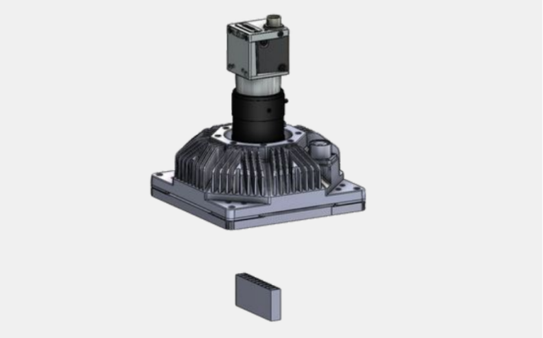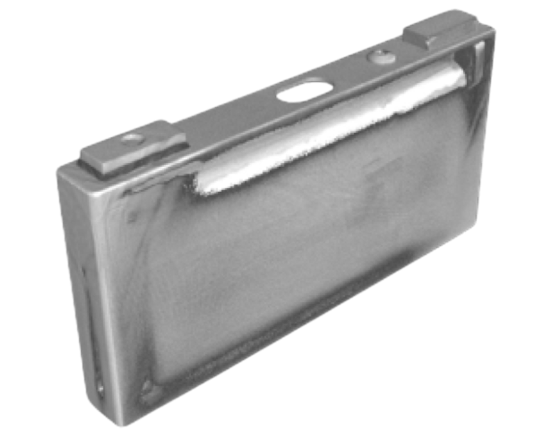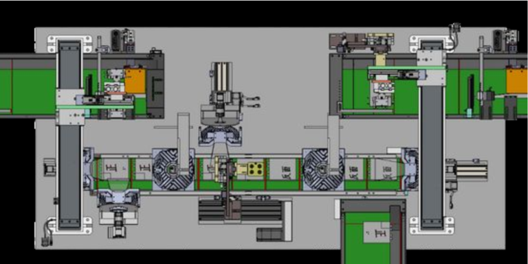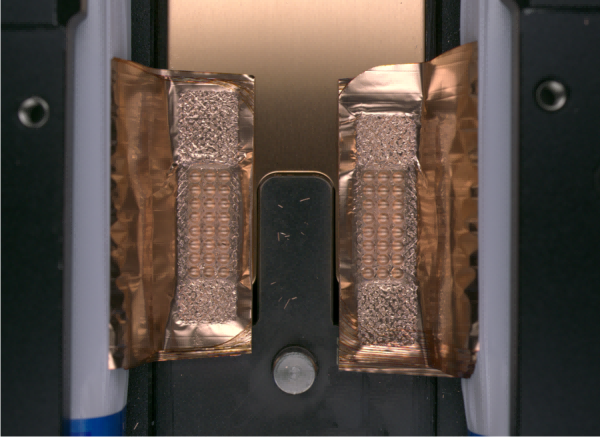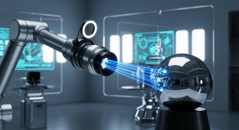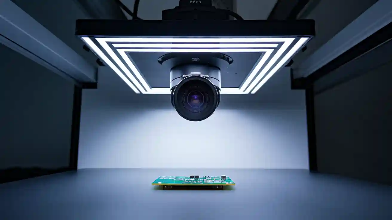
Coaxial lighting in machine vision uses a semi-transparent mirror or beam splitter to direct coaxial light onto the object, resulting in uniform, shadow-free illumination. This approach plays a vital role in automated inspection systems, especially for detecting surface flaws on reflective or curved materials. Coaxial lighting addresses issues like surface glare, uneven illumination, and the challenge of inspecting flat or recessed features. About 18.3% of systems in the market rely on coaxial lighting, which enhances inspection quality by improving visibility of subtle defects. The coaxial light machine vision system ensures reliable results in demanding inspection environments.
Key Takeaways
- Coaxial lighting directs light and camera along the same axis to create even, shadow-free illumination on flat, reflective surfaces.
- This lighting method reduces glare and shadows, making it easier to detect small surface defects like scratches or contamination.
- Choosing the right light wavelength and proper system alignment improves image clarity and defect detection accuracy.
- Coaxial lighting works best for inspecting flat, shiny objects but may need to be combined with other lighting for curved or uneven surfaces.
- Regular calibration and maintenance keep the system reliable, ensuring consistent, high-quality inspection results over time.
What Is Coaxial Light?
Principle
Coaxial lighting works by aligning the light source and the camera along the same optical axis. The system uses a semi-transparent mirror or a beamsplitter to direct light from a source straight onto the object. The camera then views the object through this same mirror, capturing the image from above. This setup ensures that the light hits the object at a perpendicular angle, which creates even illumination across the surface.
Coaxial lighting provides uniform surface illumination without glare. This method controls the angles of incidence and reflection, making it ideal for inspecting reflective or subtly featured objects. The coaxial light machine vision system uses a diffuse LED or fiber light source aimed at a beamsplitter. The beamsplitter reflects some of the light onto the part, while the camera observes the part through the same optical path. This arrangement results in very even surface illumination with minimal glare, which is crucial for accurate machine vision inspection.
The wavelength of the light used in coaxial lighting also affects imaging results. Longer wavelengths, such as red or infrared, penetrate materials more deeply than shorter wavelengths like blue. For example, infrared light can reveal internal features in semi-transparent objects, such as populated PCBs or bulb filaments. The choice of wavelength impacts image contrast, detail visibility, and defect detection. Material composition and color also influence how different wavelengths affect contrast and penetration. Selecting the right wavelength in a coaxial light machine vision system improves image clarity and enhances the detection of defects.
Key Components
A coaxial lighting system contains several essential parts:
- Light Source: Most systems use diffuse LEDs or fiber optic lights. The choice of light source affects the quality and intensity of illumination.
- Beamsplitter or Semi-Transparent Mirror: This component directs the light onto the object and allows the camera to view the object through the same optical path.
- Camera: The camera captures images through the beamsplitter. The alignment of the camera and light source is critical for achieving uniform illumination.
- Housing and Mounting Hardware: These parts hold the components in place and protect them from dust and vibration.
| Component | Function |
|---|---|
| Light Source | Provides diffuse, even illumination |
| Beamsplitter/Mirror | Directs light and aligns optical paths |
| Camera | Captures images through the beamsplitter |
| Housing/Mounting | Ensures stability and protection |
Coaxial lighting systems often include filters or polarizers to control reflections and improve image quality. Matching the wavelength of the light source to the camera sensor’s sensitivity can further enhance performance. For example, CMOS cameras respond well to infrared light, making IR coaxial lighting useful in low-light or high-speed inspections. Using polarizers with coaxial ring lights can reduce glare, but may also lower light intensity. Balancing wavelength selection and lighting geometry helps optimize image quality in machine vision applications.
Tip: Always consider the material and color of the object when selecting the wavelength for coaxial lighting. This choice can make a significant difference in contrast and defect visibility.
How Coaxial Light Machine Vision System Works
Optical Path
A coaxial light machine vision system uses a unique optical path to achieve precise inspection. The system projects light directly along the same axis as the camera. A semi-transparent mirror or beam splitter sits in the optical path. This component reflects the light from the source down onto the object. The camera then views the object through the same mirror, sharing the exact optical axis as the illumination. This coaxial arrangement ensures that the light hits the object perpendicularly, which eliminates shadows and reduces glare.
Other machine vision lighting setups often shine light from different angles. These setups can cause unwanted shadows or bright spots, especially on flat or shiny surfaces. In contrast, coaxial lighting aligns both the illumination and viewing paths. This alignment allows the system to highlight fine surface details, such as scratches or marks, that other lighting methods might miss. The beam splitter’s partial reflection and transmission make it possible for both the light and the camera to use the same path. This design is essential for inspecting reflective or transparent materials with high clarity.
Precise alignment of the optical path is critical. Technicians must mount the coaxial illuminator and beam splitter accurately. Proper alignment reduces light loss and ensures even illumination. When the optical path is not aligned, the system can lose up to 75% of the light, making coaxial lighting ineffective. Careful adjustment and calibration help maintain image quality and uniformity, which are vital for reliable inspection results.
Note: The use of polarizing filters in the optical path can further reduce internal reflections and improve image contrast, especially when inspecting polished or metallic surfaces.
Setup
Setting up a coaxial light machine vision system involves several important steps. Each step ensures the system delivers uniform illumination and high-quality images for inspection tasks.
-
Identify Inspection Requirements
Determine the types of defects and surface features that need inspection. Understanding the object’s material and surface helps select the right lighting components. -
Select Components
Choose suitable coaxial illuminators and compatible beam splitters. Look for features like adjustable intensity and focus. Make sure the light source provides uniform intensity and the correct color temperature for the application. -
Mount the Illuminator
Install the coaxial illuminator along the camera’s optical path. The light source must align perfectly with the camera to ensure coaxial illumination. -
Align the Beam Splitter
Position the beam splitter so it directs light evenly onto the inspection surface. Accurate alignment is essential for uniform illumination and effective defect detection. -
Adjust Light Intensity and Angle
Fine-tune the light’s intensity and angle to optimize contrast. Adjustments help the system detect different types of defects on various surfaces. -
Calibrate the System
Use sample objects with known defects to calibrate the system. Calibration ensures the coaxial light machine vision system can reliably detect flaws. -
Test and Optimize
Continuously test the setup with different surfaces and defect types. Make further adjustments as needed to maintain optimal performance.
| Method/Technique | Description | Key Points |
|---|---|---|
| Diffuse Dome Light | Illuminates from nearly an entire hemisphere, providing a large solid angle of illumination. | Effective on specular, curved, and topographic surfaces; requires close placement to maintain intensity. |
| Flat Diffuse Light | Provides a highly diffuse source with a central viewing port, allowing front or projection lighting. | Offers uniform illumination over larger fields of view; scalable sizes; effective at longer working distances. |
| Coaxial Light with Diffuse Sources | Combines coaxial lighting with diffuse sources placed close to the inspection surface. | Maintains uniform angular distribution and intensity; suitable for flat and angled surfaces. |
| Cube Beam Splitter + Rectangular Light Design | Uses a cube beam splitter and rectangular lights for uniform illumination of specular objects. | Optimizes system size and uniformity; addresses challenges with curvature and size. |
Placing diffuse lights close to the inspection surface helps maintain intensity and uniformity. The correct lens focal length also prevents vignetting, which can affect image quality. Larger dome lights work well for big fields of view but may be bulky and expensive.
Tip: Always calibrate the system after any adjustment to the optical path or lighting components. This practice ensures the coaxial light machine vision system continues to deliver accurate and reliable inspection results.
Advantages of Coaxial Lighting
Uniform Illumination
Coaxial lighting delivers highly uniform illumination across the entire surface of an object. The system directs light along the same axis as the camera, which ensures every part of the inspection area receives consistent brightness. This uniformity plays a key role in machine vision applications, especially when inspecting flat, reflective, or translucent materials. Operators often notice that coaxial illumination reveals surface defects such as scratches or imperfections that other lighting methods miss. The even lighting improves image quality and makes it easier to detect subtle flaws.
Consistent coaxial illumination leads to more accurate and reliable optical measurements. This consistency is essential for quality control in manufacturing, where reproducible results matter most. For example, coaxial-brightfield illumination increases image texture and enhances the ratio of direct surface reflection to subsurface scattered light. This improvement allows for better 3D height reconstruction and more precise inspection outcomes.
Shadow and Reflection Control
Coaxial lighting stands out for its ability to minimize shadows and reflections during inspection. The system aligns the light source with the camera’s optical axis, using a semi-transparent mirror to provide direct, even illumination. This approach eliminates uneven lighting and reduces both shadows and glare, which often interfere with image clarity and contrast.
- Coaxial illumination allows for precise detection of surface defects and fine details, even on highly reflective or specular surfaces.
- The reduction of shadows and reflections decreases visual noise, which improves inspection accuracy and enables thorough machine vision analysis.
- By producing high-quality images, coaxial lighting supports defect detection algorithms and lowers false positive rates in automated inspection systems.
Manufacturers in industries such as electronics and automotive rely on coaxial lighting for rapid, reliable inspection. An automotive parts producer reported a 25% reduction in overlooked surface defects after switching to coaxial illumination. This improvement highlights the value of coaxial lighting for quality control and consistent inspection results.
Tip: Combining coaxial lighting with other methods, such as diffuse dome lighting, can balance uniformity and contrast, further enhancing defect visibility while maintaining low false alarms.
Applications in Machine Vision

Ideal Use Cases
Coaxial lighting provides a powerful solution for visual inspection tasks that require high precision. This method works best for surface inspection of flat, shiny, or reflective materials. Engineers often select coaxial lighting when they need to reveal surface defects that other lighting systems might hide. For example, it excels at detecting scratches, micro-cracks, or contamination on polished metals, semiconductor wafers, and display glass. The system directs light vertically along the camera axis, which converts glare into useful information and highlights flaws that would otherwise remain invisible.
Coaxial lighting outperforms ring or dome lighting in applications where the detection of defects on mirror-like or highly polished surfaces is critical. It transforms glare into contrast, making even sub-micron scratches or flow lines visible without creating hotspots. This approach ensures reliable quality control in demanding environments.
Industry Examples
Many industries rely on coaxial lighting for automated inspection and quality assurance. The electronics manufacturing sector uses coaxial systems for PCB inspection, where it verifies the presence of components, checks pin orientation, and inspects reflective copper pads. This lighting method also supports label and barcode reading, as well as optical character verification. In industrial settings, coaxial lighting highlights fine cracks on shiny metals and reveals subtle features on difficult surfaces.
- Electronics manufacturing: PCB inspection, component verification, and pin quality checks.
- Semiconductor industry: Wafer inspection and contamination detection.
- Automotive: Surface inspection of polished metal parts for scratches or defects.
- Printing and packaging: Print and silk screen inspection for uniformity and clarity.
- Plastics: Cosmetic inspection of mirror-finish plastic parts.
Coaxial lighting enables high-contrast imaging for visual inspection, especially when surface inspection requires the detection of subtle flaws. Adjustments in lighting geometry and wavelength, such as using red light to enhance copper contrast, further improve image quality. While coaxial lighting handles most flat and reflective surfaces, engineers may choose other techniques for recessed features. This flexibility ensures that inspection systems deliver consistent results and maintain high product quality.
Coaxial Lighting vs. Other Systems
Performance
Coaxial lighting stands out for its ability to deliver stable and uniform illumination. This system directs light perpendicular to the object’s surface using a beamsplitter. As a result, it reduces shadows and glare, which helps reveal defects on reflective surfaces. Many machine vision systems rely on coaxial illumination for accurate and repeatable inspections. The consistent lighting improves the visibility of small flaws and supports reliable quality control.
Other lighting systems, such as ring lights and in-line illumination, also provide on-axis lighting. However, ring lights can create circular glare, and in-line illumination may suffer from stray light and reduced light throughput. Telecentric illumination uses collimated light to enhance edge contrast and measurement repeatability. This method often surpasses coaxial lighting in precision, especially for curved or reflective parts. Telecentric systems, though, are larger, more expensive, and sensitive to alignment.
Note: Coaxial lighting offers reliable performance for most flat, reflective surfaces, but telecentric illumination may be better for high-precision measurement tasks.
Suitability
Coaxial lighting works best for flat, shiny, or reflective objects. It is less effective on curved or uneven surfaces because the light cannot reach all areas evenly. The system requires the object to be smaller than the illumination area and needs a close working distance. These factors limit its flexibility in some applications.
Polarization filters can help reduce glare on flat surfaces, but they do not work as well on curved objects. Adjusting the lighting geometry, such as moving the light source off-axis, can help control reflections that coaxial lighting alone cannot manage. Users should consider the object’s shape, size, and surface when choosing between coaxial and other lighting systems.
| Lighting System | Best For | Limitations |
|---|---|---|
| Coaxial Lighting | Flat, reflective surfaces | Less effective on curved/large objects |
| Ring Light | General-purpose, easy to mount | Can create circular glare |
| Telecentric | Precision measurement, edges | Bulky, costly, needs precise alignment |
Tip: For large or uneven objects, combining coaxial lighting with other methods can improve inspection results.
Best Practices for System Implementation
Selection
Choosing the right coaxial lighting system requires careful evaluation of several factors. Engineers should:
- Identify the application type. Flat surfaces, cylindrical objects, or transparent materials each need different lighting strategies.
- Consider the surface material and finish. These properties affect how light reflects and whether glare will occur.
- Evaluate the type and size of defects to detect. This step helps determine the needed lighting intensity and uniformity.
- Assess the inspection environment. Physical space and ambient lighting can influence performance.
- Match the light source’s spectral output with the camera sensor’s sensitivity. This match improves detection efficiency.
- Understand the geometry between the sample, light, and camera. Proper geometry optimizes contrast and reduces unwanted reflections.
- Choose the right light structure or pattern, such as a coaxial ring light, based on the object’s shape.
- Use filters to block or pass certain wavelengths. Filters help reduce interference from ambient light.
- Ensure the lighting system can be mounted and adjusted easily for fine-tuning.
- Test and calibrate the setup before full deployment. This step confirms optimal contrast and defect detection.
Tip: Always select lighting that supports the specific features to be inspected and the requirements of quality control.
Installation
Proper installation ensures consistent performance and reliable inspection results. Technicians should:
- Mount the coaxial illuminator along the camera’s optical path.
- Align the beam splitter to direct light evenly onto the inspection surface.
- Adjust light intensity and angle to optimize contrast for different surfaces.
- Confirm compatibility with the imaging system, including mounting and optical alignment.
- Integrate the lighting with automated inspection setups to enhance quality control.
A well-installed system reduces errors and supports long-term stability.
Maintenance
Routine maintenance keeps coaxial lighting systems operating at peak performance. Key practices include:
- Clean the light source and optical components regularly. Dust and residue can degrade lighting quality.
- Monitor lamp lifespan and replace lamps before they expire. This step ensures consistent illumination.
- Inspect wiring and electrical connections to prevent failures.
- Test and calibrate the system periodically using sample defects.
- Adjust light intensity and camera exposure as needed to maintain image quality.
- Use diffusers and filters to improve contrast and reduce reflections.
Note: Consistent maintenance extends the life of the system and supports reliable defect detection in demanding environments.
Coaxial lighting delivers uniform illumination and high image quality, making it a valuable choice for machine vision systems. Engineers select this method for inspection tasks that demand precise detection of minor defects and consistent results.
- Coaxial lighting works best for reflective surfaces where quality and accuracy matter most.
- Adjustable intensity and careful calibration improve inspection outcomes.
- Automated systems benefit from reliable defect detection and stable quality control.
Applying best practices ensures long-term performance and maintains high inspection standards.
FAQ
What makes coaxial lighting different from other lighting methods?
Coaxial lighting directs light along the same axis as the camera. This setup creates even, shadow-free illumination. Other methods often produce shadows or glare, which can hide small defects.
Can coaxial lighting inspect curved or uneven surfaces?
Coaxial lighting works best on flat, reflective surfaces. It may not provide uniform illumination on curved or textured objects. Engineers often combine it with other lighting techniques for complex shapes.
How does wavelength selection affect inspection results?
The wavelength of the light source changes how materials appear in images. Red or infrared light can reveal features beneath the surface. Blue light highlights fine surface details. Proper selection improves defect detection.
Is coaxial lighting suitable for high-speed inspection?
Yes. Coaxial lighting provides stable, uniform illumination. This stability supports high-speed cameras and fast-moving production lines. Consistent lighting ensures reliable image capture and accurate inspection.
What maintenance does a coaxial lighting system require?
Technicians should clean optical components regularly. They must check and replace light sources as needed. Routine calibration ensures the system maintains image quality and defect detection accuracy.
See Also
An In-Depth Look At Cameras Used In Machine Vision
The Impact Of Structured Light On Machine Vision Performance
A Comprehensive Guide To Electronics In Machine Vision
Understanding Optical Filters And Their Use In Machine Vision
Exploring Dimensional Measurement Techniques Within Machine Vision
