Ask any manufacturing engineer who has deployed a conventional machine vision system on a production line with reflective parts, and you will hear a version of the same story: the system works during the setup demonstration. It works on the sample parts used for algorithm development. Then it goes into production, and within weeks the false rejection rate climbs, the false acceptance rate follows, and a vision specialist is called in to re-tune the illumination that was perfectly calibrated six months ago.
The cause is almost always the same: specular reflection. Polished metal, coated glass, chrome-plated surfaces, battery electrode foil, and ceramic-coated components all share the property that light reflecting off their surfaces does not scatter uniformly. Instead, it reflects directionally — and that direction changes with surface angle, with part position on the conveyor, and with the microscopic surface geometry of the specific defect you are trying to detect. Fixed illuminators, by definition, cannot adapt to any of these changes. The result is an image where the defect sits in a glare-saturated blind spot exactly where detection matters most.
This article explains the physics of why reflective surfaces defeat fixed-hardware machine vision, and how software-defined illumination — specifically, programmable multi-angle illumination with deep learning inference — resolves each failure mode at the source.
Key Takeaways
- Specular reflection creates blind spots that are physically impossible for fixed-angle illumination to avoid — the reflection angle is determined by the surface geometry, not by the inspection system’s designer.
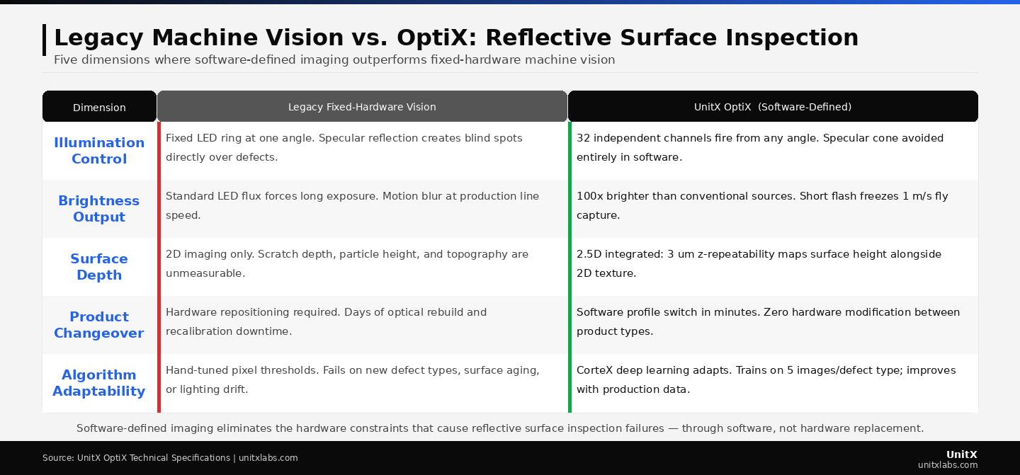
- Software-defined imaging with 32 independent illumination channels can select angles that avoid the specular cone for any surface geometry, without any physical hardware modification.
- 2.5D depth measurement at 3 μm z-repeatability detects surface height variations — scratches, particles, and raised contaminants — that are invisible in 2D imaging of reflective surfaces.
- Deep learning segmentation trained on multi-angle image data achieves detection accuracy on reflective surfaces that rule-based algorithms cannot match, because the richer image data provides sufficient discriminative signal for pixel-level classification.
The Physics of Why Reflective Surfaces Break Fixed-Hardware Vision
Specular Reflection and the Blind Spot Geometry
When a light source illuminates a rough matte surface, photons scatter in all directions according to a roughly Lambertian distribution — the camera sensor receives light regardless of its position relative to the illuminator. This is why fixed-angle LED ring illuminators work reliably on painted, anodized, or sandblasted surfaces. The physics cooperates with the hardware constraint.
Polished and coated surfaces behave according to the law of reflection: the angle of the reflected beam equals the angle of the incident beam, relative to the surface normal. A single-angle illuminator hitting a mirror-finish surface produces a reflected beam that travels in one specific direction — and if the camera sensor is not precisely at that angle, it receives near-zero signal from the surface. What the camera does see is an extremely bright specular highlight in the one location where the geometry happens to align, and a very dark image everywhere else.
A surface scratch changes the local surface normal at the defect location. If the scratch orientation happens to redirect the specular beam toward the camera, the scratch appears as a bright streak — detectable. If the scratch orientation redirects the beam away from the camera, the scratch appears as a dark region against a dark background — invisible. Whether a specific defect is detectable depends entirely on its orientation relative to the fixed illumination geometry, which is why fixed-illuminator inspection of reflective surfaces produces inconsistent defect capture rates that cannot be resolved by algorithm tuning alone. (NIST — Surface and Interface Metrology)
How Coating Variation Compounds the Problem
Industrial parts with surface coatings — chrome plating, PVD coatings, anodized finishes — add a second layer of complexity. The coating thickness is never perfectly uniform across the part surface, and thickness variation changes the optical path length through the coating. This produces interference effects that create apparent color and brightness variation across the surface image, even when no defect is present. A rule-based algorithm cannot distinguish between brightness variation caused by a coating defect and brightness variation caused by legitimate coating thickness variation — both appear as anomalous pixel values in the image.
The false rejection rates that result from this ambiguity are a well-documented production problem. In chrome-plated automotive trim inspection, false rejection rates of 10–20% are not unusual with conventional single-angle machine vision, representing significant scrap cost and, critically, operator attention fatigue that reduces the reliability of the human secondary inspection that is typically used to recover falsely rejected parts.
The Moving Surface Problem
Fly capture — inspecting parts at production line speed without stopping — introduces a third physical constraint. Conventional strobe illumination achieves sharp images of moving parts by using a very short flash duration that freezes the image. However, a short strobe pulse from a single illumination angle produces only one image frame per trigger event. To capture multiple illumination angles for a moving part, either the part must stop — eliminating the throughput advantage of inline inspection — or multiple cameras must be positioned at each angle — multiplying cost and calibration complexity.
For reflective surfaces, this constraint means that the most capable inspection strategy (multi-angle sequential illumination) is incompatible with the most efficient production configuration (continuous flow) when using fixed-hardware illumination. The only way to resolve both requirements simultaneously is to move the illumination control from hardware to software.
How Software-Defined Illumination Eliminates Each Failure Mode
Programmable Angle Selection: Avoiding the Specular Cone
The core function of software-defined illumination for reflective surface inspection is the ability to select illumination angles that avoid placing the specular reflection cone between the illuminator and the sensor. Because the specular reflection geometry for a given surface is predictable from the surface normal distribution, an inspection engineer can compute — or empirically discover through parameter search — the specific illumination angles at which the camera receives defect-scattered light rather than specular-reflected glare.
OptiX provides 32 independently controlled illumination channels, each addressable in intensity and firing sequence. For a mirror-finish metal surface, the inspection recipe might activate channels at shallow grazing angles that reveal surface topography through differential shadowing, combined with channels at angles just outside the specular cone that produce contrast between defect edges and the smooth surface. This illumination pattern is defined in software, stored as a named profile, and deployed by updating a configuration parameter — not by moving any physical hardware.
The practical consequence is that a single OptiX installation can handle a reflective surface and a matte surface in the same production run, switching between their respective illumination profiles in the time it takes to update a configuration value. For Tier 1 automotive suppliers running mixed chrome-and-painted part schedules, this eliminates the optical reconfiguration downtime that would otherwise be required between product types.
2.5D Depth Measurement: Making Invisible Defects Measurable
Scratches and particle contamination on reflective surfaces are detectable by conventional 2D imaging only when they produce a visible contrast difference against the background. On a mirror-finish surface, a 5 μm scratch may produce no detectable 2D contrast under any single-angle illumination condition — but it produces a measurable surface height discontinuity that is physically present regardless of the illumination angle.
OptiX’s 2.5D capability computes surface height from the multi-angle photometric data using shape-from-shading principles. By comparing how the surface responds to illumination from different angles simultaneously, the system extracts a depth map with 3 μm z-repeatability — making the scratch’s physical geometry measurable even when its 2D optical signature is below detection threshold. This depth information is passed to CorteX as an additional channel alongside the standard image data, giving the deep learning model a physically meaningful dimension that it can use to distinguish surface features from surface defects. (IEEE — Deep Learning 3D Defect Detection Using Photometric Stereo Illumination)
Sub-Millisecond Multi-Angle Capture During Fly
Software-defined illumination control resolves the moving-surface multi-angle capture problem through timing. Because OptiX channels are independently addressable in firing time, multiple illumination angles can be synchronized in rapid succession with sequential camera exposures. At 100x conventional illumination brightness, each individual channel flash is short enough that part movement during the flash is negligible at 1 m/s line speed — preventing motion blur — while the total multi-angle sequence completes in a single pass without stopping the line..
The result is a full multi-angle image set acquired at 1 m/s line speed from a single OptiX station. No part stops, no secondary inspection station is required for multi-angle coverage, and no synchronization of multiple camera systems is needed. The entire multi-angle acquisition is controlled by the OptiX firmware and exposed to the inspection engineer as a single configurable capture recipe. This is what enables 100% inline coverage at production throughput on reflective surfaces — a capability that is physically impossible with conventional single-channel illumination at line speed.
Software-defined imaging addresses each dimension where fixed-hardware vision fails on reflective surfaces — from illumination geometry to algorithm adaptability — through architectural changes that shift control from hardware to software.
The Deep Learning Layer: Why Richer Image Data Changes Detection Accuracy
What Multi-Angle Input Does for the AI Model
A deep learning segmentation model trained on single-angle images of reflective surfaces learns to work around glare — but it cannot detect what is hidden within it. The model’s accuracy ceiling is set by the information ceiling of its training images. Multi-angle image fusion fundamentally changes this ceiling: the model now receives images in which glare is not a constraint, depth is encoded as an additional feature channel, and surface geometry is visible in a way that was physically inaccessible before.
CorteX, trained on OptiX multi-angle images, achieves deep learning segmentation accuracy on reflective surfaces that is not achievable by the same model architecture trained on single-angle input. The reason is not the algorithm — it is the information density of the training data. The model has more to learn from and more to work with at inference time.
The practical outcome is measurable in production: CorteX achieves a false acceptance rate target of 0% on reflective surface defects that conventional rule-based algorithms detect at 70–85% rates under ideal conditions, and at significantly lower rates under the surface variation and illumination drift conditions of real production.
Sample Efficiency on Rare Reflective-Surface Defects
Reflective surface defects tend to have low natural production frequencies — the surface treatment processes that produce mirror finishes are typically well-controlled, and defects appear rarely. This creates a data scarcity problem: a defect type that appears once per 50,000 parts cannot generate the labeled dataset needed for robust deep learning detection from production sampling alone.
CorteX’s minimum training requirement of 5 images per defect type substantially reduces this barrier. For defect types where even 5 real examples are not readily available, FleX-Gen generates synthetic defect images with OptiX-consistent multi-angle imaging characteristics. A synthetic scratch on a chrome surface, generated by FleX-Gen, has the depth signature, reflectance variation, and angular response pattern that OptiX would produce on a real scratch — meaning CorteX trained on it learns a physically accurate defect representation. FleX-Gen augmentation has achieved up to 9x reduction in false rejection rates in production deployments by preventing CorteX from overfitting to the limited variation in small real defect datasets. Learn more about this capability on the FleX-Gen product page.
Specific Application Cases
Battery Electrode Foil Inspection
Lithium-ion electrode foil is among the most challenging reflective inspection targets in precision manufacturing. The foil surface — typically aluminum or copper with a micron-scale roughness profile and a coating of active material slurry — must be inspected for pinholes, contamination particles, coating holidays, and edge damage at line speeds that reach several meters per second in high-volume cell production.
Fixed-angle illumination on foil surfaces produces massive specular reflection from the metallic substrate and inconsistent contrast from the coating layer. OptiX’s programmable angle selection eliminates the specular component by firing channels at angles that produce differential contrast between pinhole edges and the surrounding foil surface — a contrast mechanism that does not rely on the specular reflection cone at all. Combined with the 3 μm depth measurement, particles as small as 10 μm are detectable as height discontinuities even when their 2D optical signature is below threshold. For the full battery inspection solution, see the battery inspection page. (U.S. DOE — Lithium-Ion Electrode Production: NDE and QC Considerations)
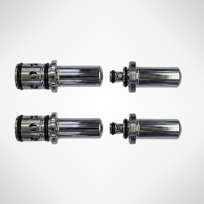
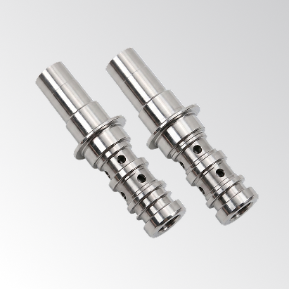
Chrome-Plated Automotive Components
Chrome-plated bumpers, door handles, trim strips, and engine components require surface quality inspection for pitting, blistering, crazing, and adhesion defects that manifest at the micron scale on a mirror-finish substrate. The reflectivity of chrome makes conventional illumination-based inspection effectively impossible — the specular component overwhelms any surface defect signature regardless of camera angle, because the camera must be roughly co-located with the illuminator to receive adequate light from the surface.
Software-defined illumination at grazing incidence angles — typically 2–8 degrees from the surface plane — produces strong differential contrast from pitting and crazing defects by shadowing their depth geometry rather than relying on reflectance contrast. OptiX’s 100x brightness advantage means that the grazing-incidence flash still provides adequate photon flux for a high-quality image at these extreme angles, where a conventional LED illuminator would produce insufficient signal. This approach is deployed across top 5 Tier 1 automotive suppliers in UnitX’s customer base. Details are available on the automotive inspection solution page.
Semiconductor Package Inspection
Solder joint inspection in semiconductor packaging requires distinguishing between geometrically perfect joints, joints with internal voids, joints with insufficient solder volume, and bridged joints — under illumination that must contend with the highly reflective surfaces of the solder alloy and the surrounding package substrate. The 2.5D capability of OptiX is particularly valuable here: solder joint height and shape are measurable from the depth map regardless of whether 2D brightness contrast is available, and CorteX segmentation classifies joint type from the combined 2D and depth input channels. (Semiconductor inspection solution)
| Surface Type | Fixed-Hardware Failure Mode | OptiX Solution Mechanism |
| Battery electrode foil | Specular glare masks pinholes and particles | Off-specular channels + 3 μm depth for particle height |
| Chrome-plated trim | Mirror surface has no stable 2D defect contrast | Grazing-incidence illumination reveals pitting by shadow |
| Solder joints | Solder alloy reflectivity confuses height with brightness | 2.5D depth map separates geometry from reflectance |
| PVD-coated components | Coating thickness variation creates false alarms | Multi-angle fusion separates coating effect from defect signature |
| Polished metal machined parts | Specular highlights saturate sensor on tooling marks | Programmable angle avoids saturation while preserving defect contrast |
Implementation Considerations for Reflective Surface Lines
Recipe Development for New Surface Types
Deploying OptiX on a new reflective surface type begins with a recipe development process that identifies the optimal illumination configuration for that specific surface. The process involves capturing images with multiple illumination subsets, analyzing which channel combinations produce maximum defect contrast for the target defect classes, and formalizing the best-performing combination as a named inspection recipe.
This recipe development typically takes 1–3 days for a new surface type, compared to the 1–3 weeks of optical hardware modification and algorithm development required for the same task in a conventional machine vision deployment. The recipe is stored in the FleX platform’s configuration library and can be deployed to any OptiX station on the network. For production lines with multiple surface types, each type has its own recipe, and the transition between recipes takes seconds.
Ongoing Accuracy Maintenance
One of the practical advantages of AI-powered inspection for reflective surfaces is that the model’s performance can be monitored and improved continuously rather than degrading silently. When CorteX encounters a defect instance that falls below the confidence threshold for a particular category, that instance is flagged for human review and, if confirmed as a true defect, is added to the training dataset. This continuous learning mechanism means that the system becomes more accurate with production experience rather than less accurate due to surface aging or recipe drift — the common failure mode of rule-based systems. Explore the full solution on the UnitX solutions page.
Common Questions
Can software-defined illumination handle surfaces that change reflectivity during production — for example, parts being lubricated or wetted?
Yes. Because the illumination recipe can be updated without hardware modification, a surface that changes reflectivity state during production can be handled by switching to the appropriate recipe at the point in the process where the state change occurs. OptiX has been deployed in wet and lubricated part inspection in automotive powertrain applications, where conventional machine vision failed entirely due to the specular behavior of the lubricant film.
Does 2.5D inspection require a longer cycle time than 2D inspection?
No. The 2.5D depth map is computed from the same multi-angle image set that the 2D inspection uses — it is an additional computational output of the same capture event, not a second inspection pass. CorteX receives the depth channel alongside the standard image channels and processes both within its normal inference throughput of 100 MP/s. The inspection cycle time for 2.5D is identical to 2D when both are performed on the same OptiX capture.
How does the system handle specular highlights that are too bright for the sensor even at minimum illumination intensity?
OptiX supports per-channel intensity control at 8-bit resolution, enabling precise attenuation of any channel that produces sensor saturation. For surface geometries where specular saturation is unavoidable from certain angles, those channels are simply excluded from the active recipe for that surface type — the multi-angle architecture ensures that sufficient non-saturated channels are available to construct a complete surface image. The system’s automatic recipe optimization identifies saturating channels during the recipe development phase and excludes them from the production configuration.