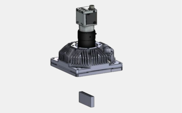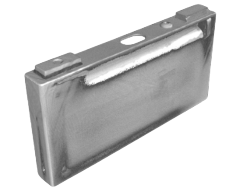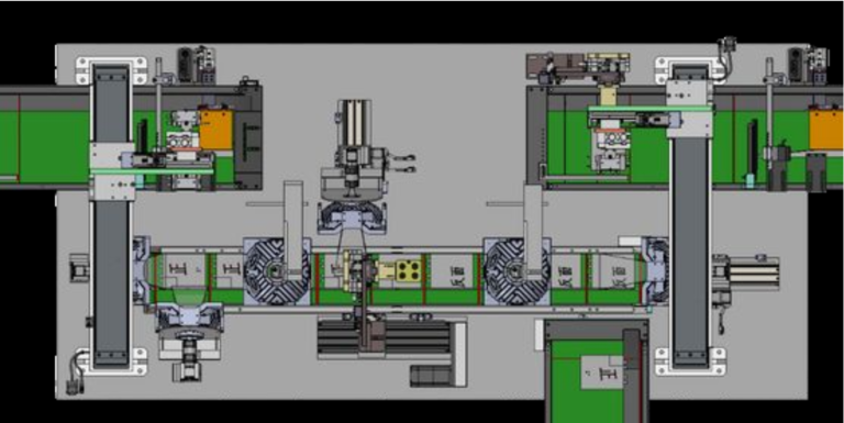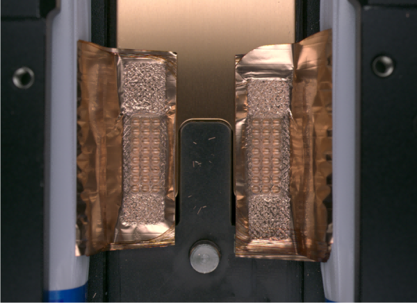
A magnification machine vision system uses optical components to enlarge or shrink the image of an object for inspection or measurement. Magnification plays a key role in how a machine vision system captures detail and ensures accurate results. Proper magnification, combined with the right lenses and system configuration, helps users see small features that standard imaging might miss. Recent studies show that magnification in telecentric lenses directly affects image size and detail. The right magnification improves accuracy and effectiveness in machine vision. Choosing the correct magnification and na settings lets the magnification machine vision system deliver precise measurements. Adjusting na and magnification also impacts how much detail the machine vision system can capture. Users must consider na, magnification, and system setup to get the best performance from a magnification machine vision system. The na of the lens, along with magnification, defines the clarity and sharpness of the image in every machine vision application. Selecting the right na and magnification ensures a reliable magnification machine vision system.
Key Takeaways
- Magnification in machine vision enlarges or reduces images to reveal small details for accurate inspection and measurement.
- Choosing the right lens type, focal length, and numerical aperture ensures clear, sharp images and precise measurements.
- Sensor size affects the field of view and image quality; larger sensors capture wider areas and more light for better detail.
- Proper calibration and alignment keep the system reliable and maintain consistent magnification and image clarity.
- Modular and motorized system parts allow flexible setup and easy adjustments to meet changing inspection needs.
Magnification Concepts
Magnification in Machine Vision Systems
Magnification in a machine vision system describes how much the system enlarges or reduces the image of an object. In machine vision, magnification is defined as the ratio between the sensor size and the field of view. The formula for optical magnification is:
Optical Magnification (m) = Sensor Size (H) / Field of View (FOV)
This ratio helps users understand how much of the object will appear on the sensor during imaging. Optical magnification plays a central role in small object inspection, where capturing fine details is essential. Higher magnification allows the system to display smaller features more clearly, which is critical for applications that require small object magnification. For example, a system with a 6.4mm sensor and a 64mm field of view has an optical magnification of 0.1x. This value means the image on the sensor is one-tenth the size of the actual object.
Tip: Selecting the right optical magnification ensures the machine vision system can resolve the smallest features needed for accurate inspection.
In industrial settings, typical optical magnification values range from 0.1x for large fields of view to higher values for close-up small object inspection. The choice of magnification depends on the size of the object, the required detail, and the application’s goals.
| Aspect | Details |
|---|---|
| Optical Magnification | Defined as image size divided by actual object size (e.g., 0.1x for a 1/2" camera with 64mm field of view) |
| Example Magnification | 0.1x (6.4mm CCD size / 64mm field of view) |
| Common Focal Lengths | 8mm, 12mm, 16mm, 25mm, 35mm, 50mm, 75mm |
| Implication | Typical magnifications range from low (~0.1x) for larger fields of view to higher magnifications for close-up inspection using lenses with focal lengths from 6.5mm to 75mm. |
Field of View and Sensor Size
The field of view (FOV) is the area of the object that the machine vision system can see at one time. Sensor size directly affects the FOV. Larger sensors capture a wider area, which is useful for inspecting big objects or scenes. Smaller sensors focus on a narrower area, making them ideal for small object inspection and small object magnification. The relationship between sensor size, FOV, and magnification is mathematical:
Field of View = Sensor Size / Magnification
When the sensor size increases, the FOV also increases if magnification stays the same. If the magnification increases, the FOV becomes smaller for the same sensor size. This balance is important for imaging tasks that require both a wide view and the ability to see fine details. In small object inspection, a smaller FOV with higher magnification helps the system capture the necessary detail.
Note: The right combination of sensor size and magnification ensures the machine vision system meets the needs of each application.
Resolution and Detail
Resolution describes how many pixels the imaging system uses to capture an object. Higher magnification increases spatial resolution by spreading more pixels over a smaller area. This improvement allows the machine vision system to detect fine details and small defects. For small object inspection, the system must resolve features that may be only a fraction of a millimeter in size. The minimum detectable feature size depends on the FOV and the number of pixels on the sensor.
- The minimum feature size = Field of View / Number of Pixels
- For reliable detection, a defect should cover at least three pixels. Some advanced systems require five to ten pixels per defect for better recognition.
Selecting the right camera resolution and optical magnification is critical for small object magnification. For example, to detect a 0.25 mm defect in a 20 mm field of view, the system needs at least 320 x 320 pixels. This setup ensures the imaging system can capture the required fine details.
Digital magnification can further enlarge the image after capture, but optical magnification provides the best clarity and accuracy. Effective magnification combines both optical and digital magnification to achieve the desired result. The na of the lens also affects resolution. A higher na allows the system to capture more light and resolve smaller features, which is important for imaging small objects.
Good lighting, proper na, and matching the lens to the sensor all help the machine vision system achieve sharp, clear images for small object inspection.
Lenses in Machine Vision
Lenses in machine vision play a central role in determining magnification, field of view, and image clarity. The right lens allows a machine vision system to capture sharp images, resolve fine details, and maintain consistent measurements. Each lens type offers unique benefits for different imaging tasks. Choosing the correct lens ensures the system meets the needs of the application, whether for general inspection or high-precision measurement.
Lens Types and Selection
Lenses in machine vision come in many types, each designed for specific imaging needs. The main types include:
- Fixed focal length lenses: These lenses provide constant magnification at a set working distance. They offer high performance and flexibility. Common uses include barcode reading, document scanning, and general parts inspection.
- Zoom lenses: These lenses allow users to adjust focal length and field of view. They work well when the object size or distance changes. However, they may not deliver the highest resolution.
- Telecentric lenses: These lenses produce parallel light rays. They keep magnification constant, even if the object moves closer or farther from the lens. This feature makes them ideal for precision measurement and metrology.
- Microscope objectives: These lenses provide very high magnification for close-up imaging. They are used for inspecting tiny features or defects.
- Wide-angle lenses: These lenses have short focal lengths and capture large scenes. They help when the machine vision system needs to see a wide area.
- Macro lenses: These lenses focus on small objects at close range. They are useful for detailed inspection.
- Liquid lenses: These lenses change focus quickly without moving parts. They suit applications with objects at different distances.
- 360° lenses: These lenses capture images from multiple angles. They help inspect objects with complex shapes.
Selecting the right lens type impacts the performance of the machine vision system. The choice depends on the object size, working distance, and the level of detail needed.
Focal Length and Magnification
Focal length is a key factor in lenses in machine vision. It determines both magnification and field of view. A longer focal length gives higher magnification and a narrower field of view. A shorter focal length provides lower magnification and a wider field of view. The right focal length helps the machine vision system capture the needed detail and area.
| Lens Type | Magnification | Field of View (FOV) | Notes |
|---|---|---|---|
| Fixed Focal Length | Fixed magnification | Fixed angular field of view | High image quality and sharpness |
| Zoom | Variable magnification | Adjustable field of view | Flexible, but may have lower resolution |
| Telecentric | Fixed magnification | Constant FOV regardless of object distance | Removes parallax errors, ideal for measurement |
| Microscope Objective | High fixed magnification | Very small FOV, close working distance | Used for tiny objects, high detail |
Focal length also affects image clarity. Longer focal lengths can increase the size of the Airy disk, which may reduce resolution if not matched with the right aperture and sensor. The machine vision system must balance focal length, aperture, and sensor size to achieve the best optical magnification and image quality.
- Short focal lengths: Best for wide fields of view and close objects.
- Long focal lengths: Best for high magnification and detailed inspection at longer distances.
- Telecentric and macro lenses: Used for precise measurement and close-up imaging.
The right focal length ensures the machine vision system captures the required detail and maintains sharp imaging.
Numerical Aperture and Depth of Field
Numerical aperture (na) measures a lens’s ability to gather light and resolve fine details. In lenses in machine vision, na directly affects both image brightness and depth of field. A higher na increases the amount of light entering the lens, making images brighter and improving contrast and visibility. This feature is important in low-light imaging.
However, increasing na reduces the depth of field. Only a thin layer of the object remains in sharp focus. This trade-off is especially important in high-magnification imaging, where users want both high resolution and enough depth of field to keep the object in focus.
- High na: Brighter images, better resolution, but shallow depth of field.
- Low na: Greater depth of field, but less light and lower resolution.
In high-magnification machine vision applications, users must balance na and depth of field. Reducing aperture size increases depth of field but decreases image brightness. The machine vision system must find the right balance to achieve clear, sharp images for inspection.
Choosing the correct na, focal length, and lens type ensures the machine vision system delivers accurate imaging and reliable results for any application.
System Components
Sensors and Image Quality
A machine vision system relies on several key components to achieve accurate magnification and na. The image acquisition unit includes the light source, lens, digital camera, and image acquisition card. These parts work together to ensure clear image capture. Lighting, such as LED or fiber optic lamps, provides the brightness needed for detailed imaging. The industrial camera, often a CCD or CMOS type, captures images with different resolutions and output signals. Sensors detect the position and state of objects, triggering image capture at the right moment.
The sensor size affects the field of view, depth of field, and light sensitivity. Larger sensors improve image quality and low-light performance, but they also increase cost and size. Pixel size influences sensitivity and resolution. Larger pixels allow more light, which helps in low-light imaging, but they also make the sensor bigger. The dynamic range of the sensor determines how well the machine vision system can handle scenes with different brightness levels. Frame rate is important for capturing moving objects without blur. Global shutters capture all pixels at once, reducing motion distortion. Vision sensors combine the camera, lighting, lens, and controller into one device, making installation easier and improving system performance.
Good sensor selection ensures the machine vision system delivers high-quality imaging and reliable magnification for any application.
Calibration and Alignment
Accurate magnification and na depend on proper calibration and alignment. The process starts with auto-calibration, where the system detects alignment marks using pattern search techniques. It then calculates the direction of the stage axis and the rotation center. Next, the system registers the reference position for alignment. It measures the target’s position and computes the correction needed to reach the reference. The control unit receives this data and adjusts the stage for precise positioning.
Camera calibration corrects lens distortion and maps pixel coordinates to real-world units. Calibration targets, like checkerboards or dot grids, help gather data from different angles. The system estimates intrinsic parameters, such as focal length and lens distortion, and extrinsic parameters, like camera position. Metrology calibration uses tools like micrometers or gauge blocks to verify measurements. Controlling environmental factors, such as lighting and temperature, keeps measurements reliable. Advanced calibration methods, including auto-calibration and optimization, improve accuracy and repeatability.
Proper calibration and alignment allow the machine vision system to maintain consistent magnification and na, ensuring precise imaging and measurement.
Modular and Motorized Options
Modular design gives a machine vision system flexibility and adaptability. Manufacturers can quickly change parts or adjust the system for new products. This modularity supports automated inspection and helps companies respond to changing production needs. By splitting components like visual sensors, actuators, and software into small units, the system can scale from a single device to a full production line. Quick reconfiguration allows the machine vision system to keep up with evolving requirements.
Motorized components, such as varifocal lenses with zoom and focus control, enable remote and precise image optimization. These features are essential for cameras in hard-to-reach places. Motorized adjustments allow dynamic changes to field of view, focus, and aperture, improving image capture and inspection accuracy. The compact and modular design of these motorized lenses supports flexible integration into various machine vision system setups. This approach enhances automation, operational efficiency, and the ability to maintain optimal magnification and na for every imaging task.
Microscopic Imaging Applications
Industrial Inspection
Microscopic imaging plays a vital role in industrial inspection. Companies use magnification to reveal small defects and features that standard imaging cannot detect. High-precision imaging tools help engineers and technicians perform non-contact inspection of products and components. Common applications include:
- Visual inspection for defects in electronics and PCB assemblies
- Soldering process checks
- Material and metallurgical analysis
- Semiconductor wafer inspection
- Assembly and rework verification
Digital and stereo microscopes allow teams to capture and share high-resolution images. These tools support documentation and collaboration across production lines. Different types of microscopes, such as optical, electron, and confocal, provide flexibility for various inspection needs. High na values improve image clarity, making defect detection more reliable.
Precision Measurement
Precision measurement relies on microscopic imaging to achieve micron-level accuracy. High-magnification systems measure shape contours, hole diameters, heights, and areas without touching the object. This non-contact inspection method ensures products meet strict tolerances. Telecentric lenses, with their parallel light rays, eliminate perspective distortion. This feature keeps measurements consistent, even if the object moves slightly.
Metrology tasks in industries like automotive, electronics, and medical devices depend on high-precision imaging. These systems use high na to gather more light and resolve fine details. Engineers trust these measurements for quality inspection during and after production. The combination of magnification, na, and telecentric optics ensures repeatable and accurate results.
Quality Control
Quality control teams use microscopic imaging to improve product reliability. Magnification reduces the real-world size each pixel represents, making it easier to spot small defects. High na and specialized optics, such as telecentric lenses, produce distortion-free images. This clarity is essential for accurate defect detection and dimensional checks.
Early defect detection helps reduce waste and ensures products meet manufacturing standards.
High-precision imaging supports sub-pixel analysis, but optimal na and magnification remain critical for reliable results. Non-contact inspection methods allow teams to check products quickly and safely. Metrology tools, combined with advanced imaging, help maintain compliance and boost confidence in the final product.
A magnification machine vision system uses magnification to reveal fine details and improve inspection accuracy. Magnification, defined as the ratio of image size to object size, affects resolution, feature detection, and measurement results. Understanding how lenses, sensor size, and na interact helps users select the right system for each application. Experts recommend matching lens magnification and focal length to the object and working distance. Careful planning and regular calibration keep the system reliable. Considering these factors ensures the magnification machine vision system delivers precise and repeatable results.
FAQ
What is the main purpose of magnification in a machine vision system?
Magnification helps the system see small features and details. It allows users to inspect tiny parts or defects that regular cameras might miss. High magnification improves accuracy in measurement and inspection tasks.
How does sensor size affect image quality?
A larger sensor captures more area and light. This improves image quality and makes it easier to see details. Small sensors focus on a smaller area, which helps when inspecting tiny objects.
Why do users choose telecentric lenses for measurement?
Telecentric lenses keep the image size constant, even if the object moves closer or farther. This feature removes measurement errors caused by perspective. Users rely on these lenses for precise and repeatable measurements.
What does numerical aperture (NA) mean in machine vision?
Numerical aperture shows how much light a lens can collect. A higher NA gives brighter images and better detail. However, it also reduces the depth of field, so only a thin layer stays in focus.
Can digital magnification replace optical magnification?
Optical magnification provides the best clarity and detail.
Digital magnification can enlarge images after capture, but it may reduce sharpness.
For accurate inspection, users should rely on optical magnification first.
See Also
Understanding How Machine Vision Systems Process Images
A Comprehensive Guide To Electronics-Based Machine Vision
Essential Features And Advantages Of Medical Vision Systems
An Introduction To Metrology Using Machine Vision Technology
