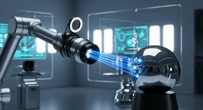
A digital fringe projection machine vision system uses a projector and a camera to measure the shape of an object without touching it.
- This system projects special patterns onto a surface and captures the deformed images to reconstruct the object’s shape in 3D.
- It provides high-speed and precise shape measurement for tasks like quality assurance, reverse engineering, and electronics inspection.
- Many industries use this technology for machine vision because it delivers accurate, non-contact shape measurement and helps improve product quality.
Key Takeaways
- Digital fringe projection systems measure 3D shapes quickly and without touching objects, using projected patterns and cameras.
- The system’s core parts include a digital projector that creates special fringe patterns and a high-speed camera that captures their deformation.
- Advanced algorithms analyze captured images to build accurate 3D models, supporting industries like manufacturing, quality control, and food inspection.
- Recent improvements like deep learning and adaptive techniques boost measurement speed, accuracy, and reliability on complex or moving surfaces.
- These systems offer fast, precise, and non-contact 3D inspection, helping improve product quality and support real-time industrial applications.
System Overview
Digital Fringe Projection Machine Vision System
A digital fringe projection machine vision system stands out as a flexible fringe projection vision system designed for high-speed, non-contact 3D measurement. This shape measurement system uses a combination of a digital projector and a camera to analyze the surface of objects. The system projects a series of sinusoidal fringe patterns onto the object. The camera captures the way these patterns deform across the surface. The flexible fringe projection vision system then uses advanced algorithms to analyze the captured images and extract phase information. This phase data allows the system to reconstruct the 3D shape of the object with high accuracy.
Digital fringe projection machine vision systems differ from other 3D measurement technologies because they use phase-shifting sinusoidal fringe patterns. The system projects several patterns with specific phase shifts, such as 0, 2π/3, and −2π/3. The camera records the intensity changes at each point. The phase at each image point is calculated from these changes. The phase information starts as a wrapped value between −π and +π. The system uses spatial algorithms to unwrap the phase and create an absolute phase map. This map is essential for accurate 3D reconstruction. Advanced phase-coding methods help solve problems like ambiguity in fringe orders, especially for objects with isolated features. The flexible fringe projection vision system combines digital projectors, extended mathematical models, and high-speed operation to deliver precise, non-contact measurements. This technique sets it apart from other methods like stereo vision or Time-of-Flight.
Core Components: Projector and Camera
The core of a flexible fringe projection vision system includes a digital projector and a high-speed camera. The projector, often based on Digital Micromirror Device (DMD) technology, generates and projects fringe patterns onto the object’s surface. The camera acts as the system’s eyes, capturing the distorted patterns as they appear on the object.
The DMD-based projector can project up to 30,000 grayscale fringe patterns per second by defocusing binary patterns. A binary phase mask enhances the quality of the fringes by creating a controlled blur. This design keeps the contrast high and the patterns clear, even at fast speeds. The projector can switch between multiple patterns quickly, which helps the flexible fringe projection vision system capture different features of the object. The system uses a high-fidelity mathematical model to transform phase data into 3D coordinates, improving measurement accuracy.
The camera in a digital fringe projection machine vision system must meet strict technical requirements. High-speed machine vision cameras allow the system to capture up to 12 million 3D pixels per second. This speed supports fast inspection on moving conveyor belts. The camera can detect tiny defects as small as 30 micrometers wide and 15 micrometers deep. Different types of cameras, such as area scan, line scan, and 3D cameras, are chosen based on the inspection task. CMOS sensors are common for high-speed jobs, while CCD sensors offer higher sensitivity for detailed inspections. The right combination of sensor type, resolution, and frame rate ensures the flexible fringe projection vision system delivers accurate results.
Sinusoidal Patterns and DMD Projectors
Sinusoidal fringe patterns play a key role in the flexible fringe projection vision system. The system generates these patterns by expanding the inverted image of a filled binary sinusoidal pattern in a specific direction. Phase shifting happens when the system switches LED backlight sources that match different binary sinusoidal patterns. This method guarantees true sinusoidal fringes, whether the projection is focused or defocused. The approach removes the need for moving parts and avoids issues like laser speckle. The system can shift phases and project patterns at very high speeds, sometimes reaching tens of MHz.
A new type of fringe pattern, called the half truncated (ht) sinusoidal fringe pattern, improves phase quality and measurement accuracy. This pattern has half its area with zero intensity, which makes binarization easier and reduces errors. Tests show that the ht-sinusoidal fringe pattern can reduce phase standard deviation error by about 29%. High-quality sinusoidal fringes are important because they improve the phase data used in 3D reconstruction. The flexible fringe projection vision system relies on these patterns for accurate and fast shape measurement.
| Advantage | Explanation |
|---|---|
| High brightness and high contrast | DMD projectors with high-power LEDs create bright, clear fringe patterns for fast, accurate 3D measurements. |
| Flexible pattern projection | The system can project any programmed image pattern, allowing precise control and diverse applications. |
| Large area coverage with high resolution | High-resolution lenses and large-format cameras cover wide areas while keeping measurements accurate. |
| Fast active pattern projection | DMD technology enables rapid pattern switching, supporting phase shift methods and boosting measurement speed. |
| Single scan image capture | Unlike laser scanning, DMD projectors capture complete images in one scan, increasing speed and reliability. |
| Mitigation of DMD mirror gap effect | Optimized optics reduce brightness loss and artifacts from mirror gaps, keeping measurement accuracy high. |
The flexible fringe projection vision system uses these advantages to deliver reliable, high-speed, and precise 3D measurements. The system’s ability to project and analyze sinusoidal patterns quickly makes it ideal for many machine vision tasks, including fringe projection profilometry. This shape measurement system supports industries that need fast, accurate, and non-contact inspection.
3D Shape Measurement Process
Fringe Projection Profilometry
Fringe projection profilometry stands as a leading technique for 3D shape measurement. This technique uses a digital projector to cast sinusoidal fringe patterns onto an object’s surface. A camera captures the deformed patterns as they appear on the object. The system then analyzes these images to extract phase information, which reveals the surface shape. Fringe projection profilometry enables non-contact, high-precision 3D measurements. The technique works quickly and does not damage the object.
The process begins with the projection of periodic fringe patterns. The camera records how these patterns deform when they hit the object’s surface. The system uses the geometric relationship between the projector and the camera to calculate the 3D coordinates of each point on the object. High-frequency fringe patterns can improve accuracy, but they often require more patterns for phase unwrapping. This step can slow down the measurement. Recent advances in fringe projection profilometry reduce the number of patterns needed, making 3D shape measurement faster without losing accuracy. These improvements help the technique measure complex and isolated objects efficiently.
Fringe projection profilometry also adapts to different surfaces. For example, adaptive fringe projection methods adjust the intensity of the projected patterns. This adjustment helps the system handle shiny or reflective surfaces, which can cause errors in phase calculation. The technique now provides robust and accurate results for a wide range of materials.
Fringe projection profilometry gives industries a reliable way to perform visualized 3d measurements. The technique supports quality control, reverse engineering, and many other applications that need fast and accurate 3d imaging.
Phase Extraction and Triangulation
Phase extraction forms the core of fringe projection profilometry. The system projects several phase-shifted fringe patterns onto the object. The camera captures these images. The system then calculates wrapped phase maps from the captured images. These maps show phase values between -π and +π. The next step is phase unwrapping, which converts the wrapped phase into an absolute phase map. This absolute phase reveals the true shape of the object.
The calibration process plays a key role in phase extraction and triangulation. The system first calibrates the camera and projector. It maps their positions in the world coordinate system using calibration parameters. The system then computes the optimal fringe angle for 3d measurements. It generates the best fringe pattern for the measurement. The projector stays fixed, but the system can virtually rotate it by adjusting calibration parameters. This step helps the system analyze fringes at the best angle for accurate 3d imaging.
The system uses mathematical models to relate phase data to real-world coordinates. It applies polynomial equations and uses calibration parameters to convert phase information into 3d coordinates. The process includes:
- Projecting sinusoidal fringe patterns onto a calibration target.
- Capturing fringe images with the camera.
- Extracting image coordinates and absolute phase values for feature points.
- Obtaining camera parameters and world coordinates.
- Using fitting polynomials to link image coordinates, absolute phases, and world coordinates.
- Solving the equations to get the spatial relationship.
- Applying phase shifting and gray coding to determine absolute phase values for the object’s surface.
- Substituting these values into the equations to reconstruct the 3d shape.
Deep learning models now help predict phase-shifted fringe images and coarse unwrapped phase maps from a single image. This improvement speeds up phase extraction and supports real-time 3d imaging.
The combination of phase extraction, system calibration, and triangulation allows fringe projection profilometry to deliver accurate 3d measurements. The technique provides detailed three-dimensional measurement data for complex shapes.
Measurement Accuracy Factors
Measurement accuracy in fringe projection profilometry depends on several factors. The quality of the projected fringe patterns affects phase calculation. High-contrast, high-frequency patterns improve accuracy but may require more images for phase unwrapping. The alignment and calibration of the projector and camera also play a major role. Precise system calibration ensures that phase data converts correctly into 3d coordinates.
Surface properties of the object can influence measurement accuracy. Highly reflective or dark surfaces may cause errors in phase extraction. Adaptive fringe projection techniques help by adjusting the intensity of the projected patterns. This adjustment reduces errors and improves measurement results.
The number of projected patterns affects both speed and accuracy. Fewer patterns mean faster measurements, but the system must still unwrap the phase correctly. Recent advances allow the system to use fewer patterns without losing accuracy. The calibration process, including the use of calibration parameters, ensures that the system maintains high measurement accuracy.
A summary table shows key factors that affect measurement accuracy in fringe projection profilometry:
| Factor | Impact on Measurement Accuracy |
|---|---|
| Fringe pattern quality | High-quality patterns improve phase accuracy |
| System calibration | Precise calibration ensures correct 3d data |
| Surface reflectivity | Adaptive projection reduces phase errors |
| Number of projected patterns | Fewer patterns speed up measurement |
| Calibration parameters | Accurate parameters improve 3d reconstruction |
Fringe projection profilometry, with its advanced phase extraction and robust calibration process, delivers accurate result and reliable three-dimensional measurement. The technique supports a wide range of applications that require fast, non-contact, and precise 3d shape measurement.
Benefits and Limitations
Speed and Precision
Digital fringe projection machine vision systems deliver fast and accurate 3D shape measurement. These systems can achieve 3D video acquisition rates between 30 Hz and 60 Hz. Some advanced systems use binary defocusing patterns to reach speeds in the tens of kilohertz. This high speed allows for quick shape measurements without sacrificing resolution or accuracy.
- Conventional systems rely on the projector’s refresh rate, usually around 120 Hz.
- Using color channels can triple the effective fringe pattern rate, but the 3D frame rate still depends on the projector.
- Binary defocusing enables much faster pattern switching, supporting rapid measurement of dynamic shapes.
| Metric/Aspect | Details/Values |
|---|---|
| Maximum relative error | Less than 5% for good precision; up to ~8.9% in less ideal conditions |
| Example system precision | 1.117% at the designed measuring distance |
| Influencing factors | Fringe period, object distance, noise level, focal length, baseline |
| System configuration | One-camera and one-projector setups are common |
The system calibration and calibration process play a key role in achieving high accuracy. Proper calibration parameters help reduce measurement errors and improve the fidelity of the final 3D shape.
Motion and Surface Challenges
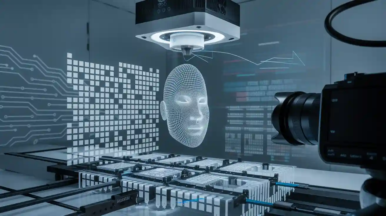
These systems handle moving objects and complex surfaces well. High-speed data acquisition lets the system capture hundreds of frames per second. This speed helps track dynamic scenes, such as facial expressions or a beating heart, with high fidelity. The use of known sinusoidal fringe patterns makes depth measurement easier, even on surfaces with complex textures.
Binary defocusing and high-speed cameras further reduce motion blur and measurement errors. For example, researchers have captured human facial expressions at 60 Hz and a beating rabbit heart at 166 Hz. These results show that the system maintains both spatial resolution and temporal fidelity during fast shape measurement. However, the projector’s refresh rate and the quality of the projected fringes can still limit performance.
Adaptive and High Dynamic Range Techniques
Adaptive and high dynamic range (HDR) techniques improve measurement reliability and accuracy, especially on challenging surfaces. Deep learning methods now combine phase unwrapping and error correction, allowing the system to achieve high accuracy with fewer phase-shifting steps. This approach helps correct errors caused by system nonlinearity, reflections, and shadows, leading to better shape measurement.
| Technique Type | Description | Purpose/Benefit |
|---|---|---|
| Adaptive Fringe Projection | Builds a model for each pixel to adjust intensity and avoid saturation. Uses a look-up table for quick adjustment. | Improves accuracy and reduces measurement errors. |
| High Dynamic Range (HDR) | Combines multiple exposures to handle surfaces with large reflectance differences. | Enhances fidelity and measurement quality. |
| Intensity Adjustment Methods | Adjusts pattern intensity to reduce the number of images needed. | Maintains accuracy while speeding up measurements. |
These adaptive methods help the system handle surfaces with high reflectivity or varying brightness. They also reduce the impact of ambient light and noise, leading to more reliable shape measurements.
Applications

Additive Manufacturing
Digital fringe projection machine vision systems play a key role in additive manufacturing. These systems project structured light onto the build surface and capture distortions to create detailed 3d imaging of each layer. Operators use these systems to detect powder bed defects, such as recoater streaks and spatter, during powder bed fusion. The system provides real-time measurement and inspection, helping identify anomalies before they affect the final part. Layer-wise surface height maps allow for precise 3d inspection and support non-destructive quality assurance.
| Aspect | Description |
|---|---|
| Application | Detects powder bed defects in additive manufacturing |
| Measurement | Creates surface height maps using structured light |
| Validation | Results confirmed by X-ray computed tomography on finished parts |
| Benefits | Enables real-time, non-destructive inspection and early defect detection |
| Industry Impact | Improves quality control and supports production-scale additive manufacturing |
Machine learning models and high dynamic range projection improve measurement accuracy and 3d imaging. These advances help manufacturers transition from prototyping to full production by ensuring reliable inspection and measurement.
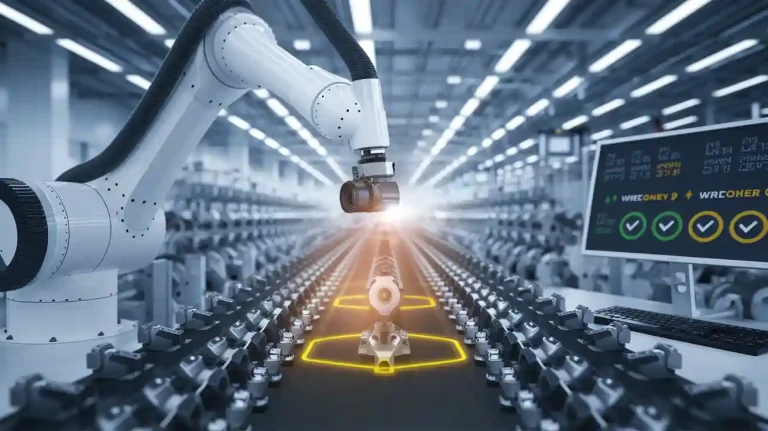
Industrial Quality Control
Many factories use digital fringe projection systems for fast and accurate inspection. The system projects phase-shifted fringe patterns onto products on conveyor lines. Cameras capture the deformed patterns, and software reconstructs 3d imaging of each item. This process enables rapid 3d inspection and measurement of structural features. Operators can detect defects, measure dimensions, and ensure products meet quality standards.
Digital fringe projection also supports vibration monitoring in rotating machinery. By projecting patterns onto rotating shafts, the system captures multi-dimensional vibrations. This non-contact measurement method offers high accuracy and helps prevent equipment failure. The technology improves inspection speed and reduces downtime in industrial environments.
Digital fringe projection systems provide reliable 3d measurements and inspection for a wide range of manufacturing tasks.
Agriculture and Food Inspection
Agriculture and food industries benefit from digital fringe projection machine vision systems. These systems use structured light to perform 3d imaging of fruits, vegetables, and packaged goods. The technology enables non-contact inspection of surface defects, size, and shape. Farmers and food processors use these systems for fast, accurate measurement and inspection on sorting lines.
Operators can identify bruises, deformities, or contamination using 3d inspection. The system supports high-speed measurements, ensuring only high-quality products reach consumers. Digital fringe projection improves food safety and reduces waste by enabling precise inspection and measurement at every stage.
Advancements
Deep Learning Integration
Deep learning has changed how digital fringe projection machine vision systems work. This technology uses neural networks to improve the technique of 3D shape measurement. Deep learning helps the system handle complex surfaces and high dynamic range objects. It also balances speed and accuracy. Many researchers have created new network architectures that use single or multiple fringe patterns as input. Some networks use reference planes, multi-stage designs, or coded patterns to boost the technique’s performance.
Recent technique improvements include time-distributed frameworks. These frameworks process several fringe patterns as temporal slices, not just as stacked images. This approach increases prediction accuracy and efficiency. Some networks can turn one or two fringe patterns into many phase-shifted patterns. Others use autoencoders or dual subnetworks to extract phase information. End-to-end frameworks combine pattern synthesis and phase estimation, but they need more computing power.
Deep learning also reduces the number of fringe images needed for the technique. Some systems now recover phase data from a single shot instead of four or more. Lightweight networks use model pruning and quantization to keep the technique fast and efficient. Special modules focus on object edges, which improves the technique’s accuracy in tricky areas.
Deep learning allows the technique to learn complex relationships without human help. This makes the system more robust and automatic.
Motion Error Reduction
Motion can cause errors in digital fringe projection machine vision systems. Many technique improvements now help reduce these errors. One method uses motor encoder data and geometric constraints to fix errors during fringe pattern capture. This technique only needs three patterns and works well even when motion is not steady.
Other technique options include object tracking, Fourier-assisted methods, and motion prediction. Object tracking uses markers or features to follow movement. Fourier-assisted technique combines single-pattern and multi-pattern approaches to update phase maps. Motion prediction estimates how objects move during the technique and compensates for errors.
Some technique improvements use advanced signal processing, like the Hilbert transform, or even deep learning to fix motion errors. Hardware upgrades, such as faster projectors and cameras, also help by making objects appear still during the technique. The phase probability equalization technique and its improved version, shifted-phase probability equalization, directly fix phase errors caused by motion. These technique options restore phase information and improve measurement accuracy for moving objects.
Future Trends
The future of digital fringe projection machine vision systems looks bright. Many new technique advancements are on the horizon. Deep learning will continue to improve phase reconstruction and speed. New hardware, such as event cameras with microsecond timing, will make the technique even faster. Computational imaging, like compressive sensing, will push recording speeds higher than 108 frames per second.
Binary defocusing and digital micromirror devices will help the technique reach tens of thousands of patterns per second. Software improvements will reduce the number of patterns needed for each 3D reconstruction, making the technique quicker. Both hardware and software will work together to break speed limits in fringe projection technique.
| Trend | Description |
|---|---|
| Deep learning | Improves phase reconstruction and technique speed |
| Event cameras | Enable microsecond-level dynamic 3D measurement |
| Compressive sensing | Increases technique speed for transient imaging |
| Binary defocusing | Allows high-speed pattern projection for the technique |
| DMD projectors | Achieve tens of kHz projection rates for the technique |
| Real-time 3D modeling | Supports virtual/augmented reality and fast manufacturing |
The market for this technique is growing, especially in Asia-Pacific. Industries like aerospace, automotive, and electronics use the technique for high-resolution surface inspection. The need for precision, real-time feedback, and AI integration drives adoption. As the technique evolves, more industries will use it for mission-critical tasks.
Digital fringe projection machine vision systems use structured light and advanced algorithms to deliver high-speed, non-contact 3D measurements.
- These systems provide benefits such as fast imaging, high precision, and lower costs compared to traditional methods.
- Users should consider object surface type, environment, measurement speed, and software features before choosing a system.
- Recent advances in deep learning, HDR imaging, and calibration methods improve accuracy and reliability for industrial tasks.
📝 Tip: Stay updated on new techniques and resources, like industry newsletters and webinars, to keep up with the latest trends in digital fringe projection technology.
FAQ
What is a digital fringe projection machine vision system used for?
A digital fringe projection machine vision system helps measure the 3D shape of objects without touching them. This shape measurement system supports fast 3d inspection and accurate result in industries like manufacturing, electronics, and food processing.
How does fringe projection profilometry work?
Fringe projection profilometry projects patterns onto an object. The camera captures the deformed patterns. The system uses phase information to create a three-dimensional measurement of the object’s surface. This technique gives high measurement accuracy and reliable 3d measurements.
Why is system calibration important for 3d shape measurement?
System calibration sets the correct relationship between the projector and camera. The calibration process and calibration parameters help convert phase data into real 3d coordinates. Good calibration reduces measurement errors and improves accuracy in 3d imaging.
What factors affect measurement accuracy in digital fringe projection?
Measurement accuracy depends on the quality of the projected patterns, the calibration process, and the surface of the object. Errors can come from poor calibration, low pattern contrast, or shiny surfaces. Adaptive techniques help improve fidelity and reduce errors.
Can digital fringe projection handle moving objects during inspection?
Yes, this technique can capture 3d measurements of moving objects. High-speed cameras and fast pattern projection reduce motion errors. The system provides visualized 3d measurements and depth measurement with good fidelity, even when objects move quickly.
See Also
Essential Insights Into Computer Vision And Machine Vision
A Comprehensive Guide To Electronics-Based Machine Vision Systems
Comparing Firmware Machine Vision With Conventional Systems
Understanding Fundamental Concepts Of Metrology Machine Vision