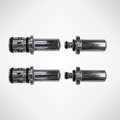
A hairline scratch on a polished metal connector looks invisible under normal lighting. The surface reflects so much light back at the camera that the scratch simply disappears into the glare. Change the angle of that light — bring it down to near-horizontal, grazing the surface, and the scratch suddenly appears bright against a near-black background. That is dark-field illumination.
It is not a new concept, but in 2026 it remains one of the most powerful and frequently misapplied lighting techniques in machine vision. This guide explains how dark-field illumination works, when to use it, how it compares to bright-field lighting, and how AI-powered imaging systems are extending its capabilities beyond what traditional setups can achieve.
Key Takeaways
- Dark-field illumination uses low-angle, grazing light to suppress reflections from flat surfaces and reveal scattered light from surface irregularities, making micro-scratches, particles, and edge defects visible against a dark background.
- It outperforms bright-field lighting on specular (mirror-like) surfaces, but degrades on matte or textured materials where background scatter overwhelms the defect signal.
- Modern AI visual inspection systems combine multi-angle illumination, including dark-field geometry — with deep learning segmentation to detect and classify defects that no single lighting mode can reliably capture.
The Physics of Dark-Field Illumination
Why Flat Surfaces Go Dark
The behavior of dark-field lighting follows straightforward reflection physics. When a light source is positioned at a shallow, grazing angle, typically 0 to 15 degrees relative to the surface, light that strikes a flat, defect-free area reflects specularly: it bounces away from the camera at an equal and opposite angle. As a result, the camera receives almost no light from these flat regions, and they appear dark.
Defects disrupt this geometry. A scratch, pit, particle, or edge creates a local surface irregularity that scatters light in multiple directions. Some of that scattered light reaches the camera lens, causing those defective areas to appear bright, often as luminous white features against a dark background. This contrast is created by scattering physics, not by color difference, brightness variation, or texture. This is why dark-field illumination can detect features that are completely invisible in bright-field imaging: the defect does not create a color or tonal change, but rather a directional change in how light bounces.
Optimal Lighting Angle for Dark Field
The illumination angle is the most critical variable in dark-field setup. For industrial machine vision applications, most practitioners use angles of 10 to 15 degrees from horizontal to achieve maximum contrast on polished metal and glass surfaces. Typical hardware implementations include low-angle ring lights, bar lights positioned at grazing incidence, or segmented coaxial arrays with controlled emission angles.
A 2025 study published in Nature Scientific Data demonstrated that grazing-angle illumination remains the most effective single-angle approach for revealing micro-scratches and pits on specular metal surfaces. However, the study also noted that static single-angle setups fail on parts with curved or complex geometries, where reflection behavior varies across the surface. This limitation drives the need for multi-angle illumination architectures in advanced AI visual inspection systems.
Dark Field vs. Bright Field: When to Use Each
Bright Field: The Default Starting Point
In bright-field illumination, light is positioned to reflect directly back into the camera from flat surface regions. Smooth, reflective areas appear bright, while features that scatter light, such as engravings, lettering, rough textures, edges will appear darker. Bright field is the most commonly used illumination technique in industrial machine vision because it produces high-contrast, information-rich images for a wide range of inspection tasks, including character verification, barcode reading, edge measurement, and color inspection.
Its weakness appears on mirror-like surfaces. When a component has a polished metal finish, bright-field illumination causes the entire surface to bloom with reflections. Subtle scratches or micro-defects that scatter light only slightly are overwhelmed by the uniform high-intensity return from the smooth background, collapsing defect-to-background contrast.
Dark Field: Where It Wins and Where It Fails
Dark-field illumination excels where bright field fails: on specular (mirror-like) surfaces where surface topography is critical. The technique is ideal for:
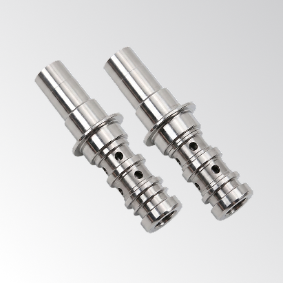
- Micro-scratches and fine lines on polished metal, glass, or wafers
- Particle contamination and surface dust on smooth components
- Edge defects, burrs, and micro-pits on machined parts
- Embossed or raised features on reflective substrates
However, the same physics that make dark field powerful also define its limits. The technique requires surface roughness (Ra) to be below approximately 0.1 µm for clean contrast. Above Ra 1 µm, matte or textured surfaces scatter light everywhere: background and defects alike, reducing the signal-to-noise ratio. Sandblasted, painted, or rough-cast surfaces are generally not suitable for dark-field inspection without additional image processing to compensate for background scatter.
| Criteria | Bright Field | Dark Field |
| Light source angle | 45–90° from surface | 0–15° from surface (grazing) |
| What the camera captures | Reflected light from flat areas | Scattered light from defects/edges |
| Background appearance | Bright (high reflectance) | Dark (near-black) |
| Best for surface finish | Matte to semi-gloss | Polished, specular (Ra < 0.1 µm) |
| Micro-scratch detection | Poor (lost in glare) | Excellent |
| Edge & pattern inspection | Good | Good for topographic edges |
| Textured surface inspection | Good | Poor (background scatter) |
| Image brightness | High (easy to expose) | Low (requires sensitive sensor) |
The Combined Approach: Maximum Defect Visibility
Research from Optics and Lasers in Engineering demonstrated that combining bright-field and dark-field illumination in a structured sequence, by acquiring both image types and computing local intensity variation between them, can achieve defect detection contrast above 90%, compared to approximately 40% for either single-mode approach on specular surfaces (per Academia.edu, Felgueiras et al., “Exploring Combined Dark and Bright Field Illumination to Improve the Detection of Defects on Specular Surfaces”).
This combined approach uses structured illumination variation rather than relying on any single fixed angle, which is the principle underlying modern software-defined imaging systems. Instead of choosing between bright field or dark field, advanced inspection hardware controls multiple independent light source segments, capturing the optimal image for each surface geometry at each inspection position.
Hardware Implementation of Dark-Field Illumination
Ring Lights at Low Angle
The most common dark-field hardware for flat-surface inspection is a low-angle LED ring light, typically a ring of LEDs mounted in a shallow cone configuration that emits light at 10–15 degrees from horizontal. Ring geometry provides uniform 360-degree grazing illumination, avoiding the directional shadow artifacts that can appear with single-direction bar lights on complex part shapes.
Working distance is a constraint: low-angle ring lights require the component to be positioned close to the light aperture (often less than 25 mm for very shallow angles), which can create mechanical integration challenges in some production-line conveyor layouts. Adjustable-height ring light mounts and programmable strobe timing are standard solutions in high-speed applications.
Segmented and Multi-Zone Illumination
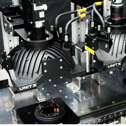
For parts with curved surfaces, non-planar geometries, or inspection requirements that span multiple defect types (some detectable only in dark field, others only in bright field), segmented multi-zone illuminators allow the system to drive different lighting zones at different angles within a single camera exposure cycle. A typical implementation cycles through three or four illumination states: grazing ring (dark field), coaxial (bright field), dome diffuse, and backlight, in under 100 milliseconds, capturing four images of the same part under different conditions.
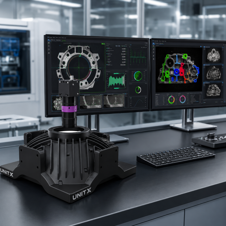
The UnitX OptiX imaging system takes this concept to its logical limit: 32 independently controllable light source channels, up to 100× the brightness of conventional illumination, and software-defined angle selection per inspection recipe. This means dark-field geometry, bright-field geometry, and multi-angle 2.5D depth imaging can all be configured in software, without changing hardware, when switching between product types or inspection requirements. The result is a single imaging front-end that replaces what traditionally required multiple dedicated inspection stations with fixed lighting setups.
Dark-Field Illumination in Semiconductor and EV Battery Inspection
Wafer Surface Inspection: Dark Field as the Standard
Semiconductor wafer inspection has used dark-field illumination as its primary defect detection modality for decades. Wafer surfaces are extremely smooth (Ra well below 0.01 µm), and the defects of interest: particles, pits, crystal defects, and scratches from handling — are precisely the types of surface irregularities that dark field reveals most effectively. A 2024 Applied Optics study demonstrated dark-field imaging with 0.5 µm detection sensitivity on large-aperture optical components, using a purpose-built scanning system to cover apertures hundreds of times larger than the camera’s instantaneous field of view (per Optica Publishing Group, “Dark-Field Surface Defects Detection Method for Multi-Surface-Shape Large Aperture Optical Components,” 2024).
For semiconductor manufacturers exploring AI-powered inspection, see UnitX’s semiconductor inspection solutions, which combine dark field geometry within the OptiX multi-angle array with CorteX AI inference for pixel-level defect classification at wafer-inspection sensitivity.
EV Battery Tab and Cell Inspection
Battery electrode tabs and cell top covers present the dual challenge; highly reflective metallic surfaces (ideal for dark field) combined with complex geometries: curved edges, weld seams, and partial overlap layers, where single-angle dark-field illumination fails. In practice, inspection systems that rely on fixed dark-field ring lights often report significant false rejection on weld bead areas, where intentional surface roughness of the weld zone scatters background dark field light and triggers false positives.
Multi-angle illumination with AI-based defect classification separates intentional weld texture (learned as “normal” during training) from the actual defect signals (delamination, pinholes, tab fold), a capability that fixed-rule dark-field systems cannot achieve. If you are specifying an inspection system for EV battery manufacturing, explore UnitX’s battery inspection solutions built around software-defined dark field and bright field multi-angle imaging.
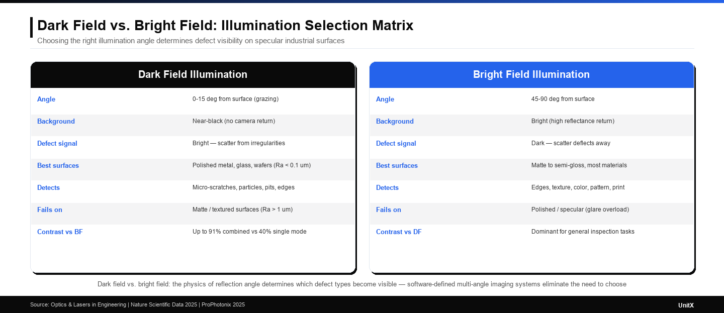
Dark field vs. bright field illumination: the physics of each technique determines which defect types become visible and which are obscured. No single angle solves every inspection challenge, which is why software-defined, multi-angle systems are replacing fixed lighting in advanced AI visual inspection.
Common Dark-Field Setup Mistakes and How to Avoid Them
Mistake 1: Using Dark Field on the Wrong Surface Finish
The most common dark-field failure mode is applying it to surfaces with Ra above 1 µm. Sandblasted, shot-peened, or rough-machined parts scatter dark-field illumination uniformly across the entire image: background and defects alike, producing high-noise images with no contrast improvement over bright-field illumination. Measure surface roughness before committing to a dark-field lighting strategy. If Ra exceeds 0.3 µm, test with combined bright/dark-field or consider coaxial or diffuse illumination instead.
Mistake 2: Inconsistent Working Distance
Dark-field contrast is highly sensitive to the angle at which light strikes the surface, and that angle changes with working distance. A ring light calibrated for a 20 mm working distance will produce a different illumination angle, and significantly different contrast, at 25 mm. In production systems with part height variation (due to fixturing tolerance or part-to-part dimensional variation), dark-field ring lights should be selected for their depth-of-field characteristics and stabilized with mechanical stops or active height control.
Mistake 3: Insufficient Camera Sensitivity
Dark-field images are inherently low-light: the camera captures only scattered light from defects, not reflected light from the entire surface. A camera sensor that performs well in bright-field inspection may produce noisy, low-SNR images in dark-field mode. Low-noise CMOS sensors with high quantum efficiency, or camera settings that increase exposure time or gain, are often required. In high-speed production lines where extended exposure is not feasible, strobe illumination with high-peak-power LED drivers is the standard solution.OptiX achieves up to 100× conventional brightness specifically to enable short, sharp strobe pulses that freeze motion while maintaining adequate dark-field illumination intensity.
Dark-Field Illumination and AI Visual Inspection in 2026
Beyond Single-Angle Setups
The trajectory of dark-field illumination in 2026 is shifting away from fixed-angle hardware configurations toward software-defined, multi-angle illumination that can be tuned per-recipe and per-part without mechanical adjustment. A 2025 Nature Scientific Data study on stroboscopic multi-illumination imaging demonstrated that combining images from multiple illumination angles, including dark-field geometry, within a single deep learning inference pipeline improves defect detection accuracy over any single-angle approach, while eliminating the need for separate inspection stations for different lighting modes.
This convergence of flexible hardware (independently controllable multi-zone illuminators) with sample-efficient AI inference (deep learning models trained on small defect datasets) is what AI visual inspection systems like UnitX’s FleX platform deliver. Instead of engineering a fixed dark-field setup for each product, quality engineers configure the illumination recipe in software, label a small set of defect images, and deploy a trained CorteX model that handles both imaging optimization and defect classification within a unified pipeline. Learn more about the FleX AI visual inspection system and how it applies adaptive illumination to eliminate the trade-offs between dark-field and bright-field approaches.
For manufacturers evaluating how to upgrade their current fixed-lighting inspection setup to a software-defined approach, contact UnitX to discuss the illumination and AI requirements for your specific defect types and surface materials.
Frequently Asked Questions
What angle should I use for dark-field illumination in machine vision?
For most specular metal and glass surfaces, 10 to 15 degrees from horizontal (grazing angle) provides the best dark-field contrast. For very smooth surfaces, such as polished wafers, even shallower angles (5–10 degrees) may improve sensitivity. The optimal angle depends on surface roughness, part geometry, and the size of the defects you need to detect; always test the specific combination before committing to a production lighting setup.
Can dark-field illumination work with AI defect detection?
Yes, and the combination is highly effective. Dark-field illumination creates high-contrast images that make micro-defects visually distinct, reducing the labeling effort required to train an AI model and improving detection accuracy. AI-powered systems like CorteX can process dark-field images to perform pixel-level deep learning segmentation and measuring defect area, boundary shape, and location, far beyond what rule-based threshold logic can achieve on the same dark field images.
What is the difference between dark-field and coaxial illumination?
Coaxial illumination (also called on-axis or bright-field coaxial) directs light along the camera axis and captures reflections from flat surfaces directly back through the lens. It produces a bright image of smooth areas and reveals surface features through reflectance differences. Dark-field illumination positions the light at a grazing angle so smooth surfaces reflect light away from the camera, revealing only the scattered light from defects. Coaxial illumination is better for surface texture inspection; while dark field is more effective for micro-scratches and particles on mirror-like surfaces.
Why does dark-field illumination fail on matte surfaces?
Matte and textured surfaces scatter incident light in all directions, regardless of angle. When dark-field illumination strikes a rough surface, both the background material and any defects scatter light toward the camera. The result is a uniformly bright, high-noise image with no meaningful contrast between defect and background. Dark field relies on specular reflection from smooth surfaces to create a dark background, this mechanism does not work when the background itself is a diffuse scatterer.
How does UnitX handle dark-field illumination in its systems?
The UnitX OptiX imaging system includes 32 independently controllable LED illumination channels that can be configured to deliver dark-field, bright-field, coaxial, dome, or multi-angle 2.5D illumination entirely in software. This means dark-field geometry is one configurable option among many — not a fixed hardware choice. When paired with CorteX’s deep learning segmentation, the system can learn which illumination angle best reveals each defect type and apply that lighting automatically per inspection step. View case studies showing real-world dark-field and multi-angle inspection results across automotive, battery, and semiconductor applications.