Camera calibration stands as a critical step for anyone seeking accuracy in a camera calibration machine vision system. Without proper calibration, distortion can affect the quality of measurements and introduce errors in vision tasks. Studies show that optimizing camera parameters reduces measurement errors in both 2D and 3D, helping meet the strict demands of machine vision systems. Uncalibrated cameras can suffer from issues like drift, debris, or sensor imperfections, leading to unreliable results. Regular calibration ensures that the camera provides consistent, distortion-free data, supporting dependable vision outcomes.
Key Takeaways
- Camera calibration removes lens distortion and sensor errors to ensure accurate and reliable measurements in machine vision systems.
- Intrinsic parameters describe the camera’s internal features, while extrinsic parameters define its position and angle; both must be calibrated for precise imaging.
- Common distortions like lens bending and perspective errors reduce image accuracy but can be corrected through proper calibration techniques.
- Using calibration targets like checkerboards and software tools such as MATLAB or OpenCV helps achieve high accuracy in camera calibration.
- Regular calibration and maintenance, including cleaning and environmental control, keep machine vision systems accurate and dependable over time.
Camera Calibration in Machine Vision Systems
Why Calibration Matters
A camera calibration machine vision system depends on precise calibration to deliver accurate results. Calibration corrects errors that come from lens distortion, sensor imperfections, and camera misalignment. When a camera captures an image, the lens can bend straight lines or stretch shapes, causing distortion. This makes measurements unreliable. Calibration removes these distortions, so the image matches the real world.
Note: Calibration is not just about fixing blurry images. It ensures that every pixel in the image represents the correct spot in the real world.
A well-calibrated camera can measure distances and angles with high accuracy. In industrial settings, calibration allows the vision system to inspect parts, measure objects, and guide robots. Without calibration, a camera can only provide limited information about a scene. Tasks like 3D reconstruction, object localization, and quality control need accurate metric measurements. Uncalibrated cameras often produce errors in these tasks, leading to unreliable results.
- Proper camera calibration significantly improves 3D model reconstruction accuracy, with errors as low as 0.09 mm in professional systems.
- Both static and dynamic calibration methods yield reliable results, with errors between 0.5 and 1.8 mm.
- Consumer-grade cameras, when calibrated, can approach the accuracy of professional systems for 3D motion analysis.
- Calibration quality directly affects the accuracy of angular displacement measurements, with small errors ranging from -0.54 to 0.19 degrees.
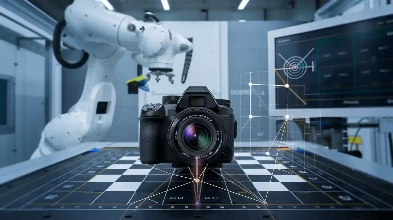
The calibration process uses known patterns, like checkerboards, to map 3D points to 2D image coordinates. This mapping allows the camera to interpret the real world correctly. Studies show that calibration can reduce measurement noise and improve precision. For example, increasing the distance between cameras in a system can lower measurement noise from 0.45 mm to 0.25 mm. Calibration also improves image quality metrics, such as sharpness and color accuracy.
Camera calibration models estimate both intrinsic and extrinsic parameters. These models help remove lens distortion and align the camera with the real world. The camera calibration matrix plays a key role in this process. It transforms points from the world into the image, ensuring that measurements are accurate and repeatable.
Intrinsic and Extrinsic Parameters
Calibration relies on two main types of parameters: intrinsic and extrinsic. Intrinsic parameters describe the internal features of the camera. These include focal length, principal point, sensor size, and lens distortion. The intrinsic matrix, also called the camera calibration matrix, contains these values. This matrix converts points from the camera’s coordinate system to the pixel grid of the image.
Extrinsic parameters define the camera’s position and orientation in the world. They show how the camera is placed relative to the objects it observes. The extrinsic matrix uses rotation and translation values to map points from the world to the camera’s view. Together, the intrinsic and extrinsic matrices allow the camera to create accurate images of the real world.
| Parameter Type | What It Describes | Example Values | Matrix Used |
|---|---|---|---|
| Intrinsic | Internal camera properties | Focal length, center | Intrinsic matrix (K) |
| Extrinsic | Camera position and orientation | Rotation, translation | Extrinsic matrix (R, T) |
The calibration process must estimate both sets of parameters. Intrinsic parameters affect how the camera forms an image. For example, the focal length changes the field of view, and the principal point sets the image center. Lens distortion parameters correct for bending or stretching in the image. Extrinsic parameters are just as important. They determine where the camera is and how it is angled. If these values are wrong, the camera will not map the world correctly.
- Intrinsic parameters, such as focal lengths and principal point coordinates, directly affect the accuracy of 3D reconstruction.
- Changes in intrinsic values cause predictable shifts in reconstructed points.
- Extrinsic parameters, like rotation and translation, have a strong impact on measurement precision.
- Small errors in extrinsic values can lead to large deviations in reconstructed coordinates.
Environmental factors, such as vibration or temperature, can change extrinsic parameters. This means that vision system calibration must be repeated if the camera moves or the environment changes. Intrinsic parameters are more stable but still need careful calibration, especially when using different lenses or camera settings.
Camera calibration models combine intrinsic and extrinsic parameters to create a complete mapping from 3D world points to 2D image pixels. The camera calibration matrix and the extrinsic matrix work together to ensure that every image the camera captures can be used for precise measurement and analysis. This is why vision system calibration is essential for any computer vision application that requires accuracy.
Tip: Regular calibration checks help maintain measurement accuracy, especially in environments where cameras may move or conditions may change.
A camera calibration machine vision system that uses both intrinsic and extrinsic calibration can achieve high accuracy in computer vision tasks. This includes 3D reconstruction, object tracking, and quality inspection. The calibration process ensures that the camera, the image, and the real world all align, making reliable vision possible.
Common Distortions and Errors

Lens Distortion
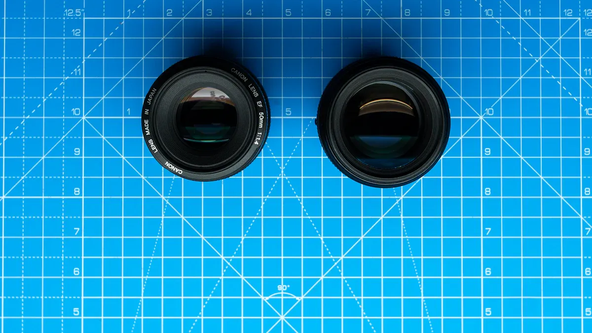
Lens distortion affects how a camera captures images. The most common types are radial and tangential distortion. Radial distortion comes from the lens shape and manufacturing process. It causes straight lines in an image to curve outward, called barrel distortion, or inward, called pincushion distortion. Tangential distortion happens when the lens is not perfectly aligned during assembly. This type bends the center and edges of images, making lines appear curved. Both types of distortion can make measurements from images less accurate. Barrel distortion often appears in wide-angle lenses, while pincushion distortion is more common in telephoto lenses. These distortions change the way a camera records the real world, so correcting them is important for machine vision.
| Component | Description |
|---|---|
| p(ulivli) | Undistorted image coordinates mapped from 3D world points |
| K | Intrinsic parameter matrix characterizing sensor parameters |
| δuli, δvli | Distortion functions representing deviations in u and v directions |
| K1, K2 | Radial distortion coefficients |
| P1, P2 | Decentering distortion coefficients |
Distortion lowers the accuracy of images by bending straight lines and reducing detail. This effect can make images blurry or geometrically incorrect, which impacts the results of machine vision tasks.
Perspective Errors
Perspective errors happen when the camera is not set up correctly. If the camera’s optical axis is not perpendicular to the measurement plane, the image will show perspective distortion. This makes objects farther from the camera look smaller. Sometimes, a circle in the real world appears as an ellipse in the image. These errors come from both the camera’s position and the way the sensor is built. Non-square pixels or a tilted sensor can also cause perspective distortion. Trapezoidal distortion, where parallel lines seem to meet or spread apart, is another result. These errors make it hard to get accurate measurements from images.
Tip: Keeping the camera perpendicular to the object and using special lenses can help reduce perspective errors, but some distortion may still remain.
Sensor Imperfections
Sensor imperfections also affect image quality. Physical defects, chromatic aberration, and vignetting can all cause distortion in images. These problems lead to blurring, color fringes, and uneven lighting. When a camera has sensor imperfections, it cannot capture sharp or clear images. This makes it harder to detect defects or measure objects accurately. The overall quality of images depends on the camera’s sensor and lens. High-quality sensors and lenses help reduce distortion and improve measurement accuracy. Using special lighting or software corrections can also help fix some sensor-related problems.
- Sensor imperfections can lower the sharpness and clarity of images.
- Good camera calibration and high-quality components are key for reliable machine vision.
Camera Calibration Methods
Calibration Targets and Boards
A camera calibration method often starts with a physical target or board. These targets help the camera relate points in the real world to points in the image. The most common patterns include checkerboards, dot grids, and coded markers. Checkerboard patterns are easy to use and work well with many calibration software tools. UV-printed checkerboards on metal surfaces give high accuracy and are easy for users to handle. Dot or circle patterns help when the camera has strong lens distortion. Coded markers, like ArUco or AprilTags, allow the camera to find its position even if part of the pattern is hidden.
| Calibration Target Type | Description | Advantages | Disadvantages | Ideal Use Cases |
|---|---|---|---|---|
| Checkerboard / Chessboard | Black and white squares | Easy to detect; widely supported | Sensitive to lighting; needs flatness | Labs, controlled settings |
| Dot / Circle Pattern | Grid of circles or dots | Accurate; robust to blur | Needs special detection | Distorted lenses, thermal cameras |
| Coded Markers (ArUco, AprilTags) | Unique binary patterns | Works with occlusion; error correction | Needs detection software | Robotics, dynamic scenes |
Material and design matter for accuracy. Metal or glass boards stay flat and last longer than paper. A white border and high-contrast patterns help the camera find features. The right calibration target depends on the camera, the environment, and the level of accuracy needed.
Tip: For beginners, a printed checkerboard is the best choice because it is simple and works with most calibration software.
Software Tools
Camera calibration relies on powerful software. MATLAB and OpenCV lead the field. MATLAB offers Camera Calibrator and Stereo Camera Calibrator apps. These tools support many patterns and help users estimate the camera matrix, correct lens distortion, and handle stereo systems. OpenCV is a popular open-source library. It supports camera calibration with checkerboards, dot grids, and coded markers. Both tools let users see errors and adjust the calibration for better results. MATLAB has a user-friendly interface, while OpenCV gives more control for custom projects. Other tools, like mrcal, focus on advanced error checking and visualization.
Note: Good calibration software lets users check errors, remove bad images, and improve the camera matrix for better accuracy.
Linear and Advanced Techniques
Camera calibration techniques fall into two groups: linear and advanced. Linear methods use the pinhole camera model. They assume a simple mapping from 3D world points to 2D image points. These techniques work well in controlled settings with little distortion. Advanced techniques add models for lens distortion and use nonlinear optimization. They start with a linear estimate, then refine the camera matrix and distortion values for higher accuracy.
| Aspect | Linear Calibration | Advanced Calibration |
|---|---|---|
| Assumption | Simple, direct mapping | Includes lens distortion |
| Accuracy | Basic corrections | High accuracy, corrects distortion |
| Data Needs | Fewer images | More images, more computation |
| Use Cases | Conveyor belts | Robotics, wide-angle lenses |
Stereo vision systems use triangulation. This technique forms a triangle between two cameras and the object. Calibration improves triangulation by correcting the camera matrix and lens distortion. This leads to better 3D measurements and more reliable results.
Calibration in Computer Vision Applications
3D Reconstruction
3D reconstruction stands as one of the most important computer vision applications. Camera calibration plays a key role in this process. The system uses calibration to compute projection matrices for each camera. These matrices help map 3D points to 2D image coordinates. The process also enables the calculation of epipolar lines, which reduces the search space for matching points between images. This step improves the accuracy of finding corresponding points. Calibration estimates intrinsic parameters and corrects lens distortions, such as radial and tangential errors. These corrections keep image points true to the real world.
- Camera calibration computes projection matrices (P1, P2) for mapping 3D points to 2D images.
- The system uses these matrices to calculate epipolar lines, improving correspondence accuracy.
- Calibration corrects lens distortions, which would otherwise degrade image point fidelity.
- Iterative optimization, like Levenberg-Marquardt, minimizes reprojection error and enhances 3D reconstruction precision.
Researchers have shown that robust calibration methods, combined with bundle adjustment and outlier removal, can reduce mean reprojection error from 47.6 to 2.13. This improvement leads to more accurate 3D models and better computer vision results.
Industrial Automation
Industrial automation relies on computer vision applications for tasks like inspection, assembly, and robotic guidance. Camera calibration enables sub-millimeter accuracy in 3D reconstruction, even with low-cost depth cameras. This level of precision is critical for manufacturing, where fast cycle times and high accuracy are required. The system captures pointclouds at optimal positions during robot motion, reducing measurement errors and improving reliability.
- 3D machine vision systems increase production efficiency and reduce errors.
- Vision-guided robotics use accurate vision systems for object identification and assembly.
- Case studies report a 26-second cycle time reduction and 97% consistency in assembly with vision-guided cells.
- Benefits include fewer defects, higher throughput, and standardized tasks.
Global calibration methods for multi-camera systems also support feature extraction and precision verification. These improvements make automated inspection and measurement more reliable.
Quality Control
Quality control in manufacturing depends on accurate computer vision applications. Camera calibration directly affects the precision of measurements. Several factors influence calibration accuracy, such as camera focus, calibration plate tilt, and the number of images used. Poor focus can reduce image sharpness, leading to errors. The tilt of the calibration plate must be considered to recover distortion and perspective parameters. Using 10 to 20 images during calibration increases success.
- Optimal camera testing environments use controlled lighting, high-resolution targets, and stable mounting.
- Space constraints and test target resolution can affect quality metrics.
- Proper configuration of test parameters, such as chart size and camera-to-chart distance, is essential for accurate calibration.
- Statistical analysis confirms that proper calibration reduces measurement errors and improves quality control outcomes.
Note: Reliable computer vision applications in quality control require careful calibration and attention to testing conditions.
Maintaining Calibration Accuracy
Challenges
Maintaining camera calibration accuracy in machine vision systems presents several challenges. Physical misalignment or bowing of calibration boards often causes problems. Even a small bend, such as 1.5 mm in a board or lid, can introduce significant distortion. Users sometimes notice that repeated calibration attempts do not improve accuracy. In some cases, results may even get worse. This happens when the calibration materials are not flat or stable. The process can correct large misalignments, but small or subtle issues still affect results.
- Physical misalignment or bowing of calibration boards
- Difficulty ensuring flatness and stability of calibration materials
- Inconsistent calibration accuracy after multiple recalibrations
- Small physical distortions that remain undetected
- Environmental factors, such as vibrations, that can shift the camera
Camera calibration accuracy can also degrade over time. Lens focus may drift because of thermal expansion or vibrations. These changes make calibration a task that needs regular attention. Proper storage and handling of calibration tools help maintain quality. Wear and tear on components can also reduce accuracy, so regular checks are important.
Best Practices
To keep camera calibration accurate, vision system operators should follow several best practices:
- Clean cameras and calibration boards with approved solvents and soft cloths to remove dust and debris.
- Lubricate mechanical parts as recommended to reduce friction and prevent wear.
- Inspect moving parts often and replace any worn components quickly.
- Operate the vision system in a stable environment with controlled temperature and humidity to minimize distortion.
- Schedule regular calibration using certified artifacts, such as gauge blocks or reference spheres.
- Recalibrate after moving the camera or making major repairs.
- Train all operators on correct calibration and maintenance procedures.
- Use genuine replacement parts and store equipment properly when not in use.
- Upgrade cameras, sensors, and lighting as technology advances.
- Use vision software to automate calibration and reduce manual errors.
Tip: Follow manufacturer guidelines for calibration frequency. High-precision applications may need monthly or quarterly calibration. Regular validation and recalibration help maintain optimal accuracy and reduce distortion in machine vision systems.
Accurate machine vision depends on reliable camera calibration. Researchers have shown that dynamic calibration targets and advanced feature extraction improve accuracy and reduce errors. Organizations can strengthen their processes by:
- Establishing independent calibration capabilities for both analog and digital cameras.
- Adopting automation and operator aids to minimize human error.
- Collaborating with industry groups to align with national standards.
Regular calibration and careful review of current practices help maintain high measurement quality. Teams should prioritize these steps to ensure consistent results in their vision workflows.
FAQ
What is the main goal of camera calibration in machine vision?
Camera calibration helps the system measure real-world objects accurately. It removes errors from lens distortion and camera misalignment. This process ensures that the camera’s images match the actual size and shape of objects.
How often should a machine vision system be calibrated?
Most experts recommend checking calibration every few months. Systems in harsh environments or with frequent movement may need monthly calibration. Regular checks help keep measurements accurate and reliable.
Can software alone fix all camera distortions?
Software can correct many distortions, but not all. Physical problems, like a bent lens or damaged sensor, need hardware repair. Good calibration uses both software and proper equipment for best results.
What happens if a camera is not calibrated?
Uncalibrated cameras often produce images with errors. Measurements may be wrong, and objects can look stretched or bent. This can cause mistakes in tasks like inspection, measurement, or robot guidance.
See Also
An Introductory Guide To Calibrating Vision System Software
Ways Machine Vision Systems Achieve Precise Alignment In 2025
Does Filtering Improve Accuracy In Machine Vision Systems
An Explanation Of Cameras Used In Machine Vision Systems
A Comprehensive Look At Dimensional Measurement In Vision Systems