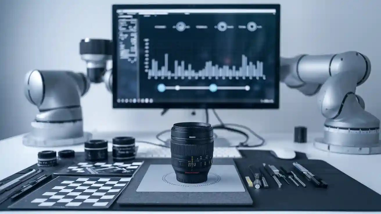
You use lens calibration in computer vision to correct lens distortion and ensure your measurements match real-world units. In robotics and automation, even a small error in vision can cause mistakes in object alignment or placement. Calibration targets, such as checkerboard patterns, help you fix perspective and distortion issues, keeping your lens calibration machine vision system accurate. Regular calibration and advanced computer vision software improve accuracy, making machine vision applications more reliable over time.
Key Takeaways
- Calibrating your camera corrects lens distortion and ensures measurements match real-world sizes, improving accuracy and reliability.
- Use special calibration patterns like checkerboards or dot grids and capture multiple images from different angles for the best results.
- Regular calibration and good lighting help avoid errors caused by environmental changes, motion blur, or poor image quality.
- Understanding intrinsic and extrinsic camera parameters is key to mapping image points to real-world coordinates accurately.
- Avoid common mistakes like using too few control points or ignoring edge distortion to keep your machine vision system precise and dependable.
What Is Calibration?
Definition in Machine Vision
You use calibration in computer vision to make sure your camera system gives you real-world measurements. In machine vision, calibration means mapping the pixel coordinates from your camera sensor to actual units like millimeters or microns. This process lets you turn what you see in an image into numbers you can trust. You often use certified calibration targets or reference objects with known sizes. These help you set up your camera calibration so your measurements match national standards. When you calibrate your camera, you remove errors and make your data more reliable. This step is important for any computer vision task that needs accurate results, such as measuring parts or checking quality.
Note: Camera calibration methods can change depending on whether you use a 2D or 3D vision system. Both types need calibration to make sure your image data lines up with real-world measurements.
Purpose and Benefits
Camera calibration gives you several key benefits in computer vision. First, it improves the accuracy and repeatability of your measurements. When you calibrate your camera, you estimate both intrinsic and extrinsic parameters. These parameters help you map 3D points in the world to 2D points in your image. This step is critical for tasks like dimensional metrology and photogrammetry.
Peer-reviewed studies show that camera calibration can reduce errors to less than 12 micrometers, with repeatability even better than one micrometer. This level of precision helps you inspect large mechanical parts in real time. You can spot problems early and make sure every part meets its tolerance. In manufacturing, this means fewer mistakes and higher quality.
You also gain confidence in your computer vision system. When you use camera calibration, your measurements become traceable and reliable. This trust is important for meeting industry rules and customer needs. You can use your calibrated camera for many tasks, such as object detection, measurement, and automated inspection.
- Key benefits of camera calibration:
- Accurate real-world measurements from image data
- Reliable and repeatable results
- Compliance with industry standards
- Better quality control in manufacturing
- Improved performance in computer vision applications
Lens Calibration Machine Vision System
Geometric and Metrology Calibration
You need a lens calibration machine vision system to get accurate measurements from your images. Calibration helps you turn what your camera sees into real-world data. You use this process to correct lens distortion and make sure your measurements are reliable. When you set up a camera calibration, you work with both geometric and metrology calibration.
Geometric calibration focuses on how your camera sees the world. You estimate the camera’s intrinsic parameters, like focal length and lens distortion, and extrinsic parameters, such as the camera’s position and angle. This step lets you relate 2D image points to 3D world coordinates. You often use calibration targets, such as checkerboards or circle grids, to help your camera find control points. These targets cover the camera’s field of view and give you enough data to estimate parameters with high accuracy. For example, concentric circle grids can help you detect control points even when there is image noise or distortion. Checkerboard patterns are popular because you can use corner detection algorithms, but they may be sensitive to noise.
Metrology calibration ensures your measurements match real-world standards. You use tools like micrometers, calipers, and gauge blocks to check your system. Sometimes, you use Coordinate Measuring Machines (CMMs) for even higher accuracy. You also calibrate other sensors, such as force, torque, temperature, and humidity sensors, to keep your measurements reliable. These steps help your lens calibration machine vision system meet industry standards and keep your results traceable.
Tip: Well-designed calibration targets, such as small planar grids, can help you achieve high precision even if your camera is slightly out of focus. You can reach low reprojection errors and keep intrinsic parameter errors under 1.3%. This means your camera calibration will work well, even in tough conditions.
Here is a list of main types of metrology calibration you might use in your system:
- Dimensional Calibration: Use tools like micrometers and CMMs to measure geometric features.
- Optical Calibration: Align optical instruments with known standards.
- Force & Torque Calibration: Check force and torque sensors for safety.
- Temperature & Humidity Calibration: Make sure environmental sensors give accurate readings.
- Pressure Calibration: Validate pressure sensors for industrial processes.
All these calibration types work together to keep your lens calibration machine vision system accurate and reliable.
Mapping Pixels to Real-World Units
You want your lens calibration machine vision system to give you measurements in real-world units, such as millimeters or inches. To do this, you need to map image pixels to real-world coordinates. Your camera sees the world in pixels, starting from the top-left corner of the image. The real world uses units like millimeters, and you need to connect these two systems.
You start by using calibration grids or targets with known spacing. You place these grids in front of your camera and capture several images from different angles. The camera calibration software finds the control points on the grid and matches them to their real-world positions. This process helps you build a mapping between pixel coordinates and real-world units. You can also use manual point-to-point mapping, where you enter the pixel and real-world coordinates into the software.
Here are some common methods you use to map pixels to real-world units:
- Use calibration grids with known spacing to create a pixel-to-real-world mapping.
- Capture multiple images of the grid at different angles to improve accuracy.
- Calibrate intrinsic parameters, such as focal length and lens distortion, and extrinsic parameters, like camera position.
- Apply perspective calibration to correct for distortion, using at least four matching points.
- Define a calibration axis to set the origin and direction for your measurements.
- Use distortion models to refine your mapping and correct for lens distortion.
When you finish calibration, your lens calibration machine vision system can translate image analysis results into real-world measurements. This is important for tasks like robotic pick-and-place, where you need to know the exact position of objects.
Note: Advanced calibration methods, such as Bayesian inference and optimization, can help you improve accuracy. These methods let you get reliable spatial measurements from your camera and sensors.
You can see the difference calibration makes in the table below:
| Measurement Aspect | Before Calibration | After Calibration |
|---|---|---|
| Average Reprojection Error | > 0.5 pixels | 0.0128 pixels |
| Root-Mean-Square Deviation of Lines | 23–65 pixels | ~1 pixel |
| Measurement Error for Obstacle Distances | N/A | < 0.5% (synthetic), < 1.6% (real) |
With proper camera calibration and image rectification, your lens calibration machine vision system can achieve high accuracy and repeatability. You can trust your measurements for quality control, automation, and computer vision tasks.
Key Concepts
Intrinsic and Extrinsic Parameters
You need to understand intrinsic and extrinsic parameters for accurate camera calibration. Intrinsic parameters describe your camera’s internal features. These include focal length, principal point, and skew coefficient. The camera calibration matrix uses these intrinsic parameters to define how your camera forms an image. You use intrinsic parameters to correct lens distortion and improve image rectification. Extrinsic parameters show your camera’s position and orientation in the world. They use rotation and translation to relate the camera to the scene. When you calibrate, you estimate both intrinsic and extrinsic parameters. This step helps you map 3D points to 2D image points and supports 3d reconstruction. If you want reliable measurements, you must get both intrinsic and extrinsic parameters right. Poor calibration or low-quality targets can reduce accuracy. Make sure your calibration target covers at least half of your camera’s field of view for the best results.
Camera Models and Distortion
Camera calibration models help you correct lens distortion and camera distortion. Most industrial cameras show some distortion, which affects your measurements. The most common types are barrel distortion, pincushion distortion, and mustache distortion. Barrel distortion curves straight lines outward, while pincushion distortion bends them inward. Mustache distortion mixes both effects, causing wavy lines. You often use checkerboard patterns to estimate distortion parameters. After calibration, you apply image rectification to straighten lines and restore true shapes. This process lets your camera give you accurate image data for computer vision tasks. The camera calibration matrix and camera calibration models work together to fix these errors.
| Type of Distortion | Description |
|---|---|
| Barrel distortion | Straight lines curve outward, common in wide-angle lenses |
| Pincushion distortion | Straight lines bend inward, opposite to barrel distortion |
| Mustache distortion | Mix of barrel and pincushion, causing wave-like bending |
| Chromatic aberration | Color fringes from colors not focusing at the same point |
3D Field Calibration
You use 3d field calibration to align multiple cameras and sensors for accurate 3d vision. This process corrects small misalignments caused by mounting or motion errors. You often use fiducial markers like checkerboards or AprilTags on flat patterns. Move the pattern through the shared view of your cameras to collect data. The calibration software then adjusts sensor parameters for the optimal configuration of 3d vision sensors. You verify accuracy by scanning objects and comparing results to your calibration data. 3d field calibration faces challenges, such as limited overlapping views and tricky surfaces like shiny or poorly textured materials. Sometimes, you use LEDs or laser pointers, but these methods take more time and skill. After calibration, the software applies image rectification to remove distortions and improve measurement accuracy. Good 3d field calibration increases data validity, helps you meet specifications, and boosts production efficiency in computer vision systems.
Tip: Always check your calibration results by comparing measurements to known standards. This step ensures your camera and sensors work together for the best image rectification and measurement accuracy.
Camera Calibration Method
Step-by-Step Process
You can follow a clear camera calibration method to get accurate measurements from your camera. This process helps you correct distortion and map image points to real-world coordinates. Here are the typical steps you should take:
-
Capture Images of a Calibration Pattern
Place a calibration target, such as a checkerboard or circle grid, in front of your camera. Take multiple images from different angles and distances. Make sure the pattern fills the camera’s field of view in each image. -
Detect Image Points and Match to Real-World Points
Use software to find the corners or centers of the pattern in each image. The software matches these 2D image points to their known 3D positions on the calibration target. -
Estimate Camera Parameters
The software calculates intrinsic parameters like focal length, principal point, and skew. It also finds extrinsic parameters, which describe the camera’s position and orientation. The software estimates lens distortion coefficients to correct for radial and tangential distortion. -
Evaluate Calibration Accuracy
Check the reprojection error. This value shows how close the projected points are to the actual image points. Lower errors mean better calibration. -
Visualize and Validate Results
Some tools let you see the camera and pattern positions in 3D. You can use this to check if the calibration looks correct.
Tip: Always use at least 10–15 images with the full pattern visible. This improves the accuracy of your camera calibration method.
Tools and Software
You have many options for camera calibration tools. These tools help you detect calibration patterns, estimate parameters, and correct distortion. Here are some of the most popular choices:
| Software Tool | Key Features | Common Use Cases |
|---|---|---|
| Matlab (Computer Vision Toolbox) | Robust 3D vision functions, camera calibration, feature detection, custom algorithms. | Research, robotics, autonomous vehicles |
| OpenCV | Image processing, camera calibration, feature detection, 3D reconstruction. | Robotics, industrial automation, research |
| TensorFlow Object Detection API | Pre-trained models, 3D vision, camera calibration tasks. | Machine learning-based vision applications |
| Adaptive Vision Studio | Camera calibration, supports many camera models, distortion corrections. | Industrial automation, machine vision systems |
You can use these tools to calibrate different types of cameras, such as projective, telecentric, or line scan cameras. Each tool supports various distortion models, from simple to complex. The calibration parameters stay valid as long as you do not change the camera or lens setup.
When you choose a calibration target, you have several options:
- Checkerboard patterns: Easy to detect, widely supported, best for controlled lighting.
- Dot or circle grids: Robust against noise and blur, good for high-accuracy needs.
- AprilGrid and CharuCo patterns: Work well even if part of the pattern is hidden or lighting changes.
- Checkerboard marker targets and PuzzleBoard: Useful for multi-camera setups and tough environments.
Note: High-quality calibration targets and good images improve your results. Make sure your calibration pattern is flat and undamaged.
Practical Tips
You can improve your camera calibration method by following expert advice. Here are some practical tips:
- Use a chessboard or dot grid as your calibration target.
- Capture at least 10–15 images from different angles and distances. Make sure the whole pattern is visible in each image.
- Detect corners or centers with sub-pixel accuracy using your software.
- Calculate intrinsic and extrinsic parameters with trusted algorithms, such as those in OpenCV or MATLAB.
- Check the reprojection error to see if your calibration is accurate.
- Use good lighting to avoid shadows and reflections. This helps your software find pattern points more easily.
- Store your images in an organized way for easy processing.
- Calibrate your lighting system and use lens filters to reduce noise and improve image quality.
- Keep your camera and calibration target stable to avoid blur.
- Use precise tooling to position parts and sensors for better inspection accuracy.
Tip: Intelligent lens systems can make calibration easier. These lenses store calibration data, such as distortion and focus settings, in a computer-readable format. You can control zoom, focus, and aperture remotely. This helps you calibrate cameras in hard-to-reach places, like robots or drones. Intelligent lens systems also update calibration data over time, so your measurements stay accurate.
You can choose between professional calibration services and in-house calibration. Professional centers use certified equipment and expert technicians. They offer a controlled environment, which gives you the highest accuracy. In-house calibration is more convenient and less expensive, but it may not match the precision of a professional service. For most industrial applications, calibrating the sensors in a controlled setting gives you the best results.
Remember: Good camera calibration is the key to accurate measurements, reliable sensors, and high image quality in your machine vision projects.
Best Practices
Accuracy Tips
You can keep your camera system accurate by following a few simple steps. Regular calibration and maintenance help you avoid errors. Always follow the manufacturer’s guidelines for your equipment. Use precise measurement tools, such as laser interferometry, to check the positioning of your sensors. Document every maintenance activity, including repairs and spare parts, so you can track performance over time.
Here are some tips to improve your calibration results:
- Calibrate your camera and sensors monthly or quarterly, especially if you use them for high-precision tasks.
- Control the environment during calibration. Keep the temperature stable and reduce vibrations. Use vibration-dampening mounts and thermal enclosures if needed.
- Use advanced software tools with step-by-step wizards. These tools guide you through the configuration and help you avoid mistakes.
- Choose the right calibration pattern for your application. Checkerboards, dot grids, and custom plates all work well for different setups.
- Make sure your lighting is even and bright. Avoid harsh shadows and reflections, as these can affect image quality and distortion correction.
- Test your configuration with simulation software before using it in production. This saves time and helps you spot problems early.
Tip: Advanced AI-powered tools can adapt to changes in temperature or vibration, keeping your camera system accurate even in tough environments.
Common Mistakes
You might run into problems if you skip important steps during calibration. Here are some common mistakes and how to avoid them:
- Using too few control points in your images. You should use at least 15–20 well-placed points across the whole image.
- Focusing only on the center of the image. Wide-angle lenses often show more distortion at the edges, so include points from all areas.
- Ignoring environmental factors. Temperature changes and vibrations can shift your camera or sensors, causing errors in your configuration.
- Allowing motion blur during image capture. Keep your camera and calibration target steady, and use good lighting to reduce exposure time.
- Overlooking sensor defects. Defective pixels can create outliers, so use software that can handle these issues.
- Not checking for wave distortion in telecentric lenses. Even special lenses need calibration correction.
| Mistake | How to Avoid It |
|---|---|
| Too few control points | Use 15–20 points, spread across image |
| Ignoring edge distortion | Place points at image edges |
| Poor lighting | Use even, diffused light |
| Motion blur | Keep camera and target steady |
| Environmental instability | Control temperature and vibration |
Remember: Regular inspection and careful configuration help you avoid these mistakes and keep your camera system reliable.
You play a key role in keeping your camera and computer vision setup accurate. Regular calibration helps you spot defects, reduce measurement errors, and keep your vision system reliable. When you align your camera and check for distortion, you prevent missed defects and keep measurements precise.
- Proper camera setup and routine checks help you avoid drift and maintain high-quality inspection.
- Following best practices extends equipment life and ensures your computer vision system works well in tough environments.
Stay updated on new calibration tools and methods. This keeps your camera and computer vision results sharp and dependable.
FAQ
What happens if you skip lens calibration?
If you skip calibration, your measurements will not match real-world sizes. You may see distorted images. Your machine vision system could make mistakes in object detection or placement. Always calibrate to keep your results accurate.
How often should you calibrate your camera system?
You should calibrate your camera system every few months. If you move the camera or change the lens, calibrate again. Regular calibration helps you keep your measurements reliable.
Can you use any pattern for calibration?
You should use special patterns like checkerboards or dot grids. These patterns have known sizes and shapes. Your software can find their points easily. Random patterns do not work well for calibration.
Does lighting affect calibration accuracy?
Yes, lighting affects calibration. Uneven or poor lighting can hide pattern points or create shadows. Use bright, even light to help your camera see the calibration pattern clearly.
What tools help you calibrate a machine vision system?
You can use software like OpenCV, MATLAB, or Adaptive Vision Studio. These tools help you find pattern points, estimate camera parameters, and correct distortion. Some tools also guide you through each calibration step.
See Also
An Introduction To Software For Calibrating Vision Systems
A Comprehensive Look At Dimensional Measurement In Vision
Fundamentals Of Metrology In Machine Vision Technologies
How Lenses Function Within Machine Vision Systems Explained
Understanding Camera Resolution Essentials For Vision Systems