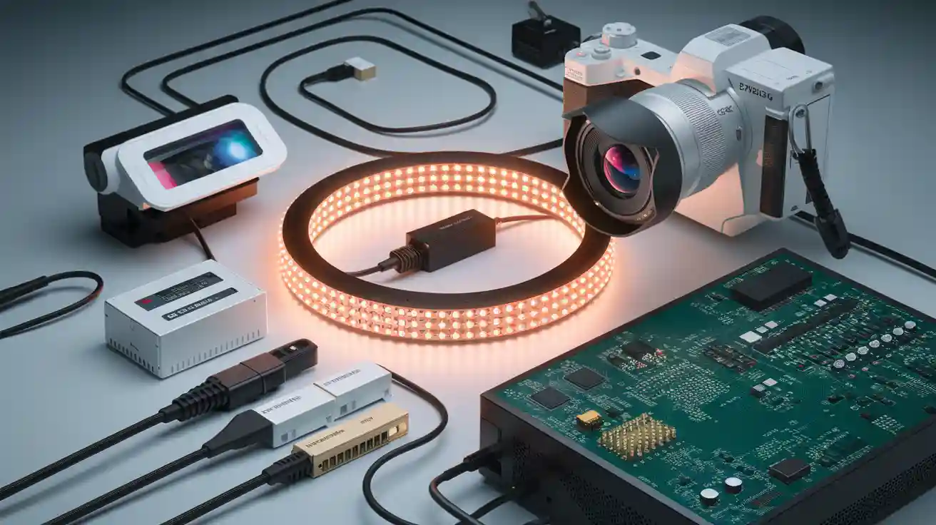
A machine vision system relies on several key components: lighting, lenses, image sensors or cameras, frame grabbers, processing units, communication interfaces, calibration tools, and integration components. Each hardware element plays a specific role in capturing, processing, and transmitting image data. Industry studies show that improvements in sensor technology, optics, and compact machine vision hardware directly boost speed, accuracy, and reliability. High-quality hardware components machine vision system setups enable precise inspection and measurement. Together, these key components ensure machine vision systems meet demanding performance requirements across different industries.
Key Takeaways
- Lighting is the foundation of machine vision systems; good lighting ensures clear images and accurate inspection results.
- Choosing the right lenses and sensors affects image sharpness, focus, and detection accuracy for reliable measurements.
- High-speed cameras and proper cables enable fast, smooth data transfer essential for real-time inspection.
- Processing units like CPUs, GPUs, FPGAs, and VPUs power image analysis; selecting the right one balances speed, power, and task needs.
- Regular calibration and careful integration of hardware components keep the system accurate, reliable, and ready for changing conditions.
Hardware Components Machine Vision System
A machine vision system depends on several hardware components working together to deliver reliable inspection, quality control, and object recognition. Each part plays a unique role in capturing, transmitting, and processing image data. Selecting the right hardware components ensures the system meets the demands of automated inspection and defect detection in industrial environments. Commercial off-the-shelf (COTS) options offer flexibility, cost savings, and compatibility, making them a popular choice for many machine vision systems.
Lighting
Lighting forms the foundation of any machine vision hardware setup. Proper illumination ensures the image sensor captures clear, high-contrast images, which is essential for accurate detection and recognition. Poor lighting can cause shadows, glare, or uneven brightness, leading to errors in inspection and quality inspection tasks. Different lighting types suit various applications, as shown in the table below:
| Lighting Type | Typical Applications | Advantages and Benefits |
|---|---|---|
| Ring Lights | Edge detection, shiny surfaces | Uniform illumination, reduces shadows and glare, compact design |
| Bar Lights | Large/elongated objects, conveyor belts | Versatile, effective for defect detection on moving objects |
| Dome Lights | Complex/irregular shapes | Diffuse, even lighting, reduces shadows and glare |
| Backlighting | Silhouette detection, transparent materials | Enhances contrast for holes, gaps, edges; useful for measurement and assembly checks |
| Diffuse Lighting | Complex shapes, reflective surfaces | Soft, even illumination, improves measurement accuracy |
| Dark Field Lighting | Surface defect detection | Highlights imperfections, reduces glare, enhances fine detail visibility |
| Multispectral Lighting | Feature detection with different wavelengths | Reveals hidden features, improves image quality and system efficiency |
| Adaptive Lighting | Dynamic environments | Adjusts illumination in real-time for consistent image quality |
Adaptive lighting systems use sensors and machine learning to maintain image quality even when ambient conditions change. This technology improves defect detection in environments like outdoor inspections or fast-moving production lines.
Tip: High-quality lighting directly impacts the signal-to-noise ratio, contrast, and focus, which are critical for reliable image acquisition and precise inspection.
Lenses and Optics
Lenses and optics determine how the system focuses light onto the image sensor. The choice of lens affects image sharpness, distortion, and measurement accuracy. Fixed focal length lenses, also called prime lenses, are common in machine vision systems because they provide consistent image quality and resolution. Adjustable aperture lenses allow users to control exposure and depth of field, which is important for inspecting objects at different heights.
Key optical parameters for lens selection include:
- Focal length: Controls image size and angle of view.
- Aperture: Regulates light entering the lens, affecting brightness and depth of field.
- Depth of field: The range where objects remain in focus.
- Shooting distance: The space between lens and object, influencing focus and clarity.
- Resolution: Ensures features to detect cover enough pixels for reliable identification.
- Sensor compatibility: The lens must match the sensor size and spectral range.
Specialized lenses, such as telecentric lenses, reduce perspective distortion and improve measurement precision. Macro lenses enable detailed close-up imaging. Addressing lens distortion is vital, as even small errors can impact automated inspection and quality inspection results.
Image Sensors and Cameras
The image sensor is the heart of every machine vision hardware system. It converts light into electrical signals, creating digital images for processing and analysis. The two main types of image sensors are CCD (Charge-Coupled Device) and CMOS (Complementary Metal-Oxide-Semiconductor). Modern CMOS sensors often outperform CCDs in speed, sensitivity, and cost-effectiveness.
| Feature | CCD Sensor Characteristics | CMOS Sensor Characteristics |
|---|---|---|
| Signal Type | Electron packets transferred across chip | Voltage converted at pixel site |
| Noise Level | Low noise, high uniformity | Moderate to high noise, pixel-to-pixel inconsistency |
| Sensitivity | Moderate, improved by microlenses | Moderate to high, improved pixel architecture |
| Dynamic Range | High, limited by blooming and well depth | Moderate, less blooming, supports high dynamic range |
| Speed | Moderate to high, limited by charge transfer speed | High speed due to on-pixel readout circuitry |
| Power Consumption | Moderate to high | Low power consumption |
| Uniformity | High uniformity due to charge transfer | Lower uniformity due to fabrication variations |
| Shutter Type | Typically global shutter | Rolling shutter common; global shutter possible |
| Size and Complexity | Larger due to off-chip ADCs | Smaller, integrated ADCs on chip |
Industrial cameras in machine vision systems must match the application’s sensor resolution and frame rate needs. The smallest feature to detect should cover at least a 3×3 pixel grid for reliable detection. High-speed cameras support fast production lines, while higher resolution cameras capture more detail for advanced recognition and defect detection tasks.
Frame Grabbers and Cables
Frame grabbers act as the bridge between cameras and processing units. They capture image data and transfer it efficiently to computers or embedded processors. Frame grabbers support high-speed data transfer, synchronization of multiple cameras, and low-latency triggering. Onboard FPGA processing can handle pre-processing tasks, reducing the load on the main processor and improving overall system performance.
Cables connect all hardware components in a machine vision system. The choice of cable affects data transfer speed, distance, and reliability. The table below summarizes common cable types:
| Cable Type | Data Transfer Speed | Key Features |
|---|---|---|
| USB3 Vision | Up to ~3 Gbps | Locking connectors, power over cable, used in various applications |
| GigE Vision | Up to 10 Gbps | Supports multiple cameras, long distances, synchronization |
| CoaXPress (CXP) | Up to 12.5 Gbps per cable | Power delivery, expandable bandwidth, industrial-grade |
| Camera Link (CL) | 2.04–6.8 Gbps | Multiple configurations, low latency, power over cable |
| Fiber Optic | Up to several kilometers | Extends cable lengths, available for multiple interfaces |
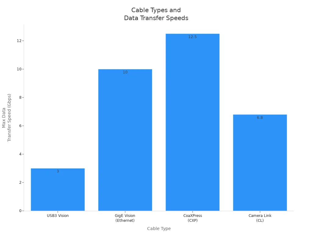
Selecting the right frame grabber and cable ensures smooth, fast, and reliable image acquisition, which is essential for real-time inspection and vision processing.
Processing Units
Processing units analyze image data and make decisions based on inspection, detection, and recognition tasks. The main types of processing units in machine vision hardware include CPUs, GPUs, FPGAs, and VPUs. Each has unique strengths:
| Processing Unit | Architecture & Characteristics | Computational Power & Speed | Power Consumption | Typical Use Cases & Strengths |
|---|---|---|---|---|
| CPU | Versatile, supports many tasks | Slower for intensive image processing | Moderate to high | Good for prototyping, user interfaces, less intensive tasks |
| GPU | Many parallel cores, excels at pixel math | Much faster for image processing | Can be power-hungry | Ideal for high-speed image processing and graphics rendering |
| FPGA | Custom programmable logic, no OS overhead | Very fast, deterministic timing | Low | Real-time, high-speed, low-latency applications |
| VPU | Specialized for vision tasks, AI integration | High-speed, energy efficient | Very low | Edge devices, real-time AI, portable systems |
CPUs handle general tasks and user interfaces, while GPUs and VPUs excel at parallel image processing and AI-driven recognition. FPGAs provide fast, deterministic processing for real-time applications. The choice of processing unit affects speed, accuracy, power consumption, and the ability to scale machine vision systems.
Note: COTS hardware components, such as lighting modules, sensors, cameras, and processing units, enable rapid deployment, cost savings, and easy integration. Compatibility between hardware components ensures scalability and reliable performance across different machine vision systems.
Communication and Interfaces
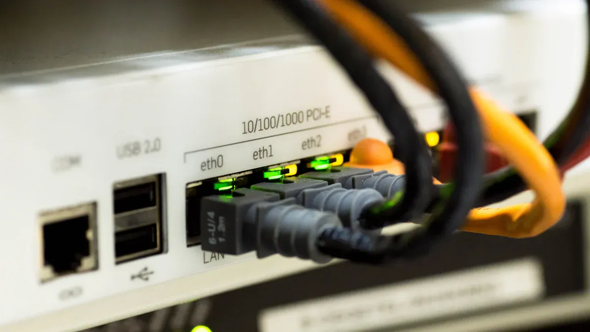
Data Transmission
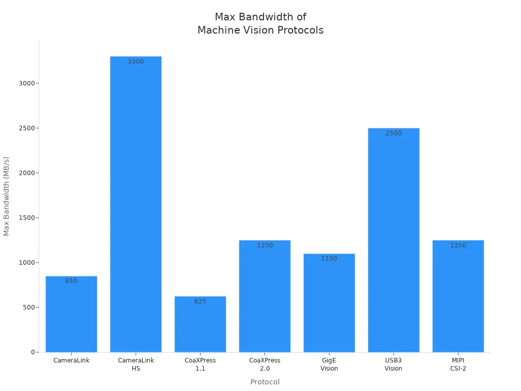
Data transmission forms the backbone of any machine vision platform. High-speed protocols allow cameras to send large volumes of image data to processing units quickly. This speed is vital for real-time applications, where delays can impact process monitoring and quality control. Technologies such as CoaXPress and Camera Link HS deliver high bandwidth and low latency, supporting fast inspection and monitoring tasks. The table below compares widely used protocols by their maximum bandwidth and cable length:
| Protocol | Maximum Bandwidth | Typical Cable Length | Notes on Usage and Features |
|---|---|---|---|
| CameraLink | Up to 850 MB/s | 4-10 m | Requires frame grabber; used in PC-based systems |
| CameraLink HS | 2100-3300 MB/s | 15 m | High-speed version; requires frame grabber |
| CoaXPress (CXP) 1.1 | 6.25 Gb/s per lane (~625 MB/s) | 40-60 m | Robust for long distances; requires frame grabber |
| CoaXPress (CXP) 2.0 | 12 Gb/s per lane (~1250 MB/s) | 30-60 m | Supports multiple cameras per frame grabber |
| GigE Vision | 115 MB/s (standard) up to 1100 MB/s (10 GigE) | Up to 100 m | No frame grabber needed; flexible networking |
| USB3 Vision | 400 MB/s (USB 3.0) up to 10-20 Gbit/s (USB 3.1/3.2) | 3-5 m (passive cable) | Widely used in embedded and PC systems |
| MIPI CSI-2 | Up to 2.5 Gb/s per lane (4 lanes up to 10 Gb/s) | Short distances (embedded) | Common in embedded/mobile systems |
Fast data transmission enables cameras to operate at high frame rates. This capability supports process monitoring and defect detection, ensuring the machine vision platform delivers accurate results with minimal delay.
Interface Standards
Interface standards ensure that different hardware modules work together within a machine vision platform. Standards like Camera Link, GigE Vision, and USB3 Vision define how devices connect, communicate, and transfer data. Newer protocols such as Camera Link HS and CoaXPress offer higher speeds and advanced features like error correction. GenICam provides a unified software layer, allowing consistent camera control and simplifying integration.
| Interface Standard | Bandwidth | Max Cable Length | CPU Usage | Power Delivery | Multi-Camera Support | System Cost | Vision Standard |
|---|---|---|---|---|---|---|---|
| FireWire (IEEE 1394) | ~80 MB/s | 4.5 m | Low | Up to 45 W | Excellent (daisy chaining) | Medium | IIDC DCAM |
| Camera Link | Up to 680 MB/s | 10 m | Medium | None | Fair | High (requires frame grabbers) | Camera Link |
| Gigabit Ethernet (GigE Vision) | ~125 MB/s | 100 m | Medium | Up to 15.4 W (PoE) | Good (IP addressable, scalable) | Medium | GigE Vision |
| USB 3.1 (USB3 Vision) | ~400 MB/s | 3 m | Low | Up to 4.5 W | Excellent (via hubs) | Low | USB3 Vision |
Hardware and software standards define cables, connectors, protocols, and programming interfaces. This approach ensures interoperability and reduces integration complexity for machine vision hardware.
Integration Components
Integration components connect all hardware modules, creating a complete machine vision platform. These components include industrial PCs, vision controllers, embedded systems, and interface peripherals such as Ethernet switches, USB hubs, and frame grabbers. Communication interfaces like serial ports and I/O modules enable integration with factory equipment and PLCs.
| Integration Component Type | Description & Role |
|---|---|
| Computing Platforms | Industrial PCs, vision controllers, embedded systems, workstation PCs, enterprise servers, cloud-based systems |
| Interface Peripherals | Ethernet switches, USB PCIe cards, USB hubs, frame grabbers for CoaXPress and Camera Link |
| Communication Interfaces | Serial and I/O ports, support for PLC integration and industrial protocols |
A reliable machine vision platform depends on careful selection and integration of these components. Engineers must plan, test, and validate the system to ensure all parts work together for accurate processing and monitoring. Skilled integration reduces errors, supports process monitoring, and improves overall system reliability.
Calibration and System Integration
Calibration Tools
Calibration tools play a vital role in ensuring accuracy and reliability in machine vision systems. Engineers use high-quality hardware, such as cameras, lenses, and sensors, that align well to reduce errors and improve repeatability. Calibration software automates data collection and analysis, making it easier to meet industry standards. Both linear and non-linear calibration methods help address different system needs. Linear methods work well for simple setups, while non-linear methods handle complex distortions for higher precision.
- Real-time calibration techniques allow systems to adjust continuously during motion or lighting changes.
- Regular validation and recalibration with reference objects keep measurements accurate over time.
- Calibration tools also account for environmental factors like temperature, lighting, and vibrations.
- Optimizing imaging parameters, such as resolution and exposure time, further improves calibration results.
Case studies show that proper calibration can reduce measurement errors from dozens of pixels to just one, boosting operational efficiency and supporting quality assurance.
System Design
Designing a machine vision system requires careful planning. Engineers must select hardware that matches the inspection task. They consider sensor type, lens choice, lighting, and filters to ensure the system meets performance goals. Software simplicity is important, as easy-to-use programs reduce setup time and errors. Scalability allows the system to grow with changing needs.
| Key Design Considerations | Description |
|---|---|
| Sensor Selection | Choose sensors based on resolution and compatibility with optics. |
| Lens Choice | Match lens focal length and aperture to imaging needs. |
| Lighting | Select lighting that provides even, clear images. |
| Filters | Use filters to block unwanted light and improve clarity. |
| Interface | Pick camera interfaces that support required bandwidth and distance. |
Environmental awareness is also crucial. Engineers must consider lighting, speed, and material properties to select the right hardware and strategies.
Machine Vision Hardware Integration
Integrating hardware components ensures the system works as a single, reliable unit. Engineers select cameras with the right frame rate and spectral response for the inspection process. They design mechanical setups that keep optics and lighting stable, even in changing temperatures. Proper installation, calibration, and testing maximize system efficiency.
Best practices include:
- Develop lighting solutions early to ensure consistent illumination.
- Address physical constraints and safety during design.
- Use standardized communication protocols for compatibility.
- Perform regular calibration and maintenance to maintain accuracy.
- Prototype and test the integrated system before full deployment.
High-quality hardware, such as advanced cameras and stable mounting, reduces errors and increases reliability. Automated inspection systems and precise alignment of cameras, fixtures, and lighting support consistent image capture. This approach lowers operational costs and supports long-term system performance.
Each hardware component in machine vision systems—lighting, lenses, sensors, processing units, and interfaces—plays a unique role in delivering clear images and accurate inspection results. To select the right hardware for machine vision applications, engineers should:
- Match sensor type and resolution to the smallest feature to detect.
- Choose lenses and lighting that fit the inspection environment.
- Use enclosures for protection in harsh settings.
- Balance speed, accuracy, and resource use for the task.
Understanding these roles helps teams design reliable systems that meet specific inspection goals and adapt to changing needs.
FAQ
What is the most important hardware component in a machine vision system?
Every component matters, but lighting often has the biggest impact. Proper lighting ensures the camera captures clear images. Without good lighting, even the best cameras and lenses cannot deliver accurate results.
How does lens selection affect image quality?
Lens choice controls focus, sharpness, and distortion. A high-quality lens matches the sensor and application. The right lens helps the system capture fine details and reduces errors during inspection.
Can machine vision systems use standard computer hardware?
Many systems use commercial off-the-shelf (COTS) hardware. Industrial PCs, standard processors, and common interfaces work well. Specialized tasks may need dedicated frame grabbers or rugged enclosures for harsh environments.
Why is calibration necessary in machine vision?
Calibration aligns the camera, lens, and lighting. It corrects errors and ensures measurements stay accurate. Regular calibration keeps the system reliable and supports quality control.
What happens if one hardware component fails?
A failed component can stop the system or cause errors. Engineers should use reliable parts and plan for maintenance. Quick replacement and regular checks help prevent downtime.
See Also
Understanding The Fundamentals Of Electronic Machine Vision Systems
How Cameras Function Within Machine Vision Technologies
The Importance Of Lighting Devices In Machine Vision Applications
Comparing Firmware-Based Machine Vision To Conventional Systems
Comprehensive Overview Of Semiconductor-Based Machine Vision Solutions