By UnitX Applications Engineering Team, Applications Engineering at UnitX · March 2026 · 9 min read
In machine vision, there’s a persistent myth: better AI means better defect detection. Upgrade your model, add more training data, tune your thresholds — and you’ll catch more defects. The assumption is that the camera is capturing all the information, and the software just needs to be smarter about extracting it.
The reality is the opposite. The fundamental limit of any inspection system is the quality of information in the images. If a defect is not visible under the current lighting conditions — if it produces no contrast, no shadow, no reflectance change that can be detected — then no AI algorithm, however sophisticated, can find it. You cannot compute information that isn’t in the image.
Software-defined lighting is the approach that solves this problem at the source: by dynamically controlling the illumination, it ensures that every class of defect is visible in at least one image in the inspection sequence. The AI then has all the evidence it needs.
Key Takeaways
- Fixed single-angle lighting creates systematic blind spots — defects parallel to the illumination direction appear invisible, while the same defects perpendicular to it are clearly visible.
- Software-defined lighting with multiple independent channels captures the same part under different illumination conditions in a single pass, ensuring every defect type is visible in at least one image.
- OptiX’s 32-channel architecture switches through up to 50 lighting schemes per second, 100× brighter than conventional light sources, enabling fly capture at 1.0 m/s without motion blur.
- The practical outcome is elimination of the most common root cause of inspection misses: defects that are simply invisible under the wrong lighting.
Why Fixed Lighting Fails: The Physics of Defect Visibility
How Light Reveals (and Hides) Defects
The visibility of a surface defect in a camera image depends on a simple physical relationship: the defect must produce a measurable difference in the light reaching the camera, compared to the surrounding acceptable surface. This difference can arise from several mechanisms: the defect absorbs more light (creating a darker region), reflects light at a different angle (creating contrast in directional illumination), or scatters light differently (creating texture contrast).
The critical point is that which mechanism dominates depends on the defect geometry and the illumination direction. A scratch — a narrow furrow in the surface — is nearly invisible when illuminated parallel to its direction (light enters the furrow and exits at the same angle as reflected light from the surrounding surface). The same scratch illuminated perpendicular to its direction shows a sharp shadow cast across the furrow — highly visible. A conventional fixed-direction ring light illuminates the scratch equally from all azimuthal angles, which means the components parallel to the scratch cancel out the components perpendicular to it, and the net contrast is mediocre in all orientations.
The Multi-Directional Problem
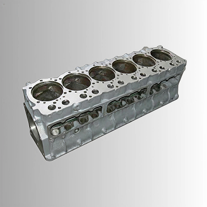
The situation becomes more complex when a part has multiple defect types with different optimal illumination requirements. Consider a die-cast component that might exhibit: surface scratches (best seen with low-angle dark field from a specific direction), porosity pits (best seen with coaxial or diffuse illumination to create shadow in the pit), and contamination (best seen with bright-field uniform illumination for color/intensity contrast). No single fixed lighting configuration is optimal for all three.
Traditional approaches to this problem require either multiple separate lighting stations (increasing line footprint and capital cost) or compromise configurations that are suboptimal for all defect types. Industry data on machine vision lighting consistently shows that lighting configuration accounts for a significant share of inspection performance — experts estimate lighting quality determines up to 70% of inspection success or failure. Software-defined lighting is the architecture that eliminates this constraint.
How Software-Defined Lighting Works
The OptiX Architecture
UnitX OptiX is built on a modular array of 32 independent LED channels, each controllable for intensity, timing, and duty cycle. Unlike a fixed ring light or bar light, where all LEDs illuminate simultaneously at constant intensity, OptiX can activate any subset of channels at any intensity level at any timing relative to the camera shutter — and switch to a completely different configuration for the next image capture within the same inspection cycle.
The result is the ability to capture multiple images of the same part under fundamentally different lighting conditions in a single pass, without stopping the part or extending the cycle time beyond what the line speed permits. OptiX supports up to 50 lighting scheme switches per second, meaning that for a part passing through the field of view in 100ms, up to 5 complete lighting configurations can be cycled — producing 5 distinct images that each highlight different defect types.
The 100× Brightness Advantage
The practical challenge with multi-lighting rapid cycling is exposure time: as you switch lighting faster, each individual exposure must be shorter to fit within the cycle. A shorter exposure means less light reaching the sensor per frame, which means more image noise and reduced sensitivity to low-contrast defects.
OptiX addresses this with LED overdrive technology that produces illumination 100× brighter than conventional LED ring lights operating in continuous mode. By concentrating the full LED power into a brief, precise strobe pulse (rather than spreading it over a long continuous exposure), OptiX delivers high signal-to-noise images even at sub-millisecond effective exposure times. At 1.0 m/s fly capture speed, a 100μs strobe pulse limits motion blur to approximately 100 micrometers — well below the resolution limit of typical surface defect detection applications.
Lighting Configurations and What Each Reveals
| Lighting Configuration | How It Works | Defects Best Revealed |
|---|---|---|
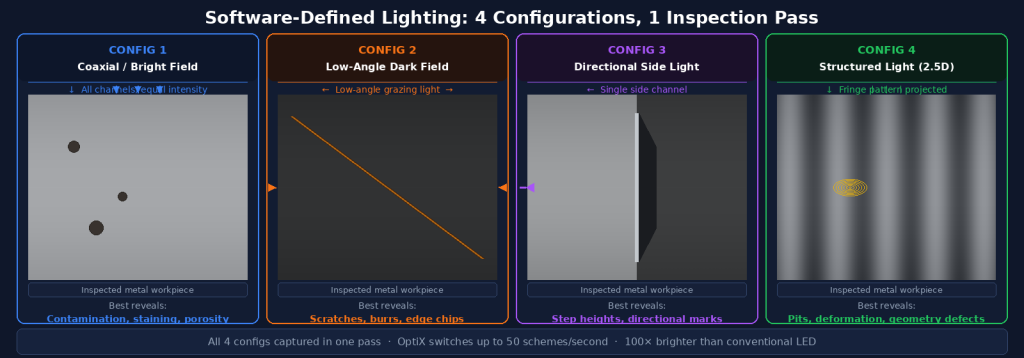
| Coaxial / Bright Field | Light aligned with optical axis; specular surfaces appear bright | Contamination, staining, color anomalies, porosity pits on smooth surfaces |
| Low-Angle Dark Field | Light at shallow angle; topographic features cast shadows toward camera | Scratches, surface texture irregularities, raised features, edge chips |
| Directional Side Lighting | Single or dual directional channels active; asymmetric illumination | Edge features, step heights, directional scratches, embossed marks |
| Structured Light (2.5D) | Fringe pattern projected; depth measured from pattern deformation | Geometric defects: pits, burrs, deformations, coating thickness variation |
| Diffuse Dome | Light from all angles simultaneously; eliminates directional shadows | Color defects, printing errors, label inspection on curved surfaces |
A Real-World Application: EV Battery Tab Welding Inspection
The Challenge
EV battery tab welding inspection is one of the most demanding surface inspection applications in manufacturing. The tabs are thin metallic foil, highly reflective, with welds that must be evaluated for: complete fusion area, absence of voids or porosity in the weld zone, absence of burrs at the tab edge, and correct dimensional positioning. Each of these defect types has different optimal illumination requirements — and the highly reflective metallic surface creates extreme specular reflection that overwhelms conventional lighting.
The Software-Defined Lighting Solution
For this application, OptiX captures four images per weld inspection cycle: one under coaxial illumination to reveal void signatures and surface contamination, one under low-angle dark field to reveal burrs and edge irregularities, one under directional lighting to reveal incomplete weld boundaries, and one structured light image to provide the 2.5D depth map for geometric confirmation. The AI model receives all four as inputs and evaluates each defect category against its corresponding evidence channel.
The inspection completes within the line cycle time for battery cell assembly — typically 200–500ms per cell — without requiring the line to stop or slow. The multi-image approach is enabled entirely by OptiX’s software-defined lighting architecture; a conventional fixed-lighting system would require either multiple separate inspection stations for each lighting type, or a compromise single-lighting configuration that misses significant defect categories.
The ROI of Better Imaging
The business case for software-defined lighting rests on two numbers: the cost of escapes and the cost of false rejects.
Every defect that escapes inspection has a cost — in warranty claims, customer returns, rework, or in safety-critical applications, product recalls. One automotive tier-1 supplier achieved $781,000 per year return per production line after deploying UnitX — a figure that reflects the combined savings from reduced escapes, reduced rework, and reduced manual inspection labor. The cost of a single recall event in the automotive or EV battery sector routinely exceeds the total investment in AI inspection across an entire factory.
Every false reject has a cost too — the part must be manually re-inspected, often accepted anyway, and the labor and handling time is spent. On high-volume lines, false rejection rates above 1–2% eliminate the labor-saving benefit of automation and erode operator confidence in the system. Software-defined lighting, by providing the imaging foundation needed for high-confidence decisions, is a direct contributor to maintaining false rejection at acceptable levels.
→ See how OptiX’s software-defined imaging integrates with CorteX AI for complete inline inspection: OptiX imaging system overview.
→ Dealing with a challenging inspection application where fixed lighting hasn’t delivered the results you need? Talk to UnitX experts — we’ll analyze your specific surface and defect types and recommend the optimal lighting configuration.
Frequently Asked Questions
How is software-defined lighting different from having multiple separate lights?
Multiple separate fixed lights (a ring light plus a bar light plus a dome light) still require either manual switching between inspection modes or simultaneous illumination that blends all lighting effects. Software-defined lighting uses a single integrated hardware unit with independently controlled channels, switching between configurations electronically at high speed with nanosecond precision relative to the camera shutter. This enables multi-image capture of a moving part in a single pass — which multiple separate fixed lights cannot do without stopping the part.
Does every application need multiple lighting configurations?
No. For applications with simple defect types on non-reflective surfaces — contamination on a matte plastic part, label printing errors, presence/absence checks — a single lighting configuration may be entirely sufficient. The value of software-defined lighting scales with application complexity: the more diverse the defect types, the more variable the surface properties, and the more reflective the material, the more significant the advantage of dynamic multi-configuration imaging.
How do you determine the right lighting configurations for a new application?
The starting point is physical analysis: examine the defect types, understand their geometric nature (scratches, pits, raised features, contamination), and match them to the illumination mechanisms that make each visible. For production deployments, this is done during the SAT (Site Acceptance Testing) process: UnitX’s applications engineers configure the lighting, capture reference images, train the initial AI model, and validate detection performance against customer-provided defect samples. The target is <1 week from system installation to validated inspection performance — the standard UnitX SAT commitment across more than 1,000 deployed systems globally.