Every manufactured part has dimensional specification: length, diameter, height, or gap, that must fall within a defined tolerance to function correctly. A connector housing that is 0.3 mm too wide will not mate with its counterpart. A battery tab that is 0.5 mm too short will fail the weld. An automotive shaft that is out-of-round by 20 µm will cause premature bearing wear.
Catching these deviations before they reach the customer used to require manual gauging: calipers, micrometers, and go/no-go gauges. Today, object dimension machine vision systems measure parts automatically, without contact, and at production speed. This guide explains how they work, the key concepts involved, and how AI-powered inspection is changing what dimensional measurement can achieve.
Key Takeaways
- Object dimension machine vision systems use cameras, lenses, sensors, and software to measure the size, shape, and geometry of parts without physical contact which replaces manual gauging at production-line speed.
- There are three main types: 1D (linear distance), 2D (planar measurement), and 3D (full spatial geometry) , each suited to different tolerance requirements and part geometries.
- Accuracy in machine vision dimensional measurement depends on calibration, sub-pixel edge detection techniques, and the quality of the imaging system, AI-powered systems can now close the gap between vision system precision and CMM-grade metrology.
What Is an Object Dimension Machine Vision System?
Definition and Core Function
An object dimension machine vision system is an automated inspection solution that captures images of manufactured parts and uses software to extract dimensional measurements from those images, converting pixel coordinates into real-world units (millimeters, micrometers, or inches) for comparison against part specifications and tolerances.
The system typically consists of:
- Camera and lens: Captures the image of the part at the required resolution and field of view
- Controlled illumination: Provides consistent, repeatable lighting to clearly reveal part edges and features
- Image processing software: Detects edges, locates features, and calculates distances, angles, and radii
- Calibration system: Converts pixel measurements into physical units with known accuracy
- Decision logic: Compares measured dimensions to tolerances and generates pass/fail signals or grading classifications
The global 3D machine vision market was valued at USD 8,027.8 million in 2025 and is projected to reach USD 22,314.5 million by 2033, growing at a CAGR of 13.7%.This growth is driven by adoption of Industry 4.0, smart factory initiatives, and increasing demand for high-precision inline inspection (per Grand View Research, “3D Machine Vision Market,” 2026). For manufacturers still relying on manual gauging, the transition to machine vision dimensional inspection represents both a quality improvement and a cost reduction.
Machine Vision vs. Manual Gauging
Manual inspection with calipers and micrometers is human-dependent, slow, and subject to inter-operator variation. A skilled inspector measuring a 50 mm shaft diameter may achieve ±0.01 mm accuracy, but only at the speed of manual operation and only during working hours. Machine vision systems can achieve similar or better accuracy at 60+ frames per second, 24/7, with no variation due to operator fatigue (per UnitX, “A Beginner’s Guide to Object Dimension Machine Vision Systems”).
Non-contact measurement also prevents damage to delicate parts such as thin-film materials, coated surfaces, and precision optical components, where a caliper jaw can cause the very defect it is intended to detect.
The Three Types of Dimensional Machine Vision Systems
1D Systems: Linear Distance Measurement
One-dimensional machine vision systems measure a single spatial parameter, typically a distance, height, or gap along a single axis. They use line sensors or point distance sensors to capture one row of pixel data at a time, computing the position of edges or features along that line.
1D systems are the fastest and least expensive option, well suited for:
- Height gauging of stamped parts on a conveyor
- Gap measurement between two components
- Wire or film thickness profiling
Their limitation is clear: they cannot capture 2D or 3D geometry. A part that has the correct height but the wrong shape will pass a 1D inspection without detection.
2D Systems: Planar Measurement and Edge Detection
Two-dimensional machine vision systems capture full image frames and extract measurements in the X and Y axes (horizontal and vertical). Edge detection algorithms locate the boundaries of part features at sub-pixel precision, enabling measurement of widths, lengths, diameters, angular positions, and geometric form.
The edge detection process works by analyzing pixel brightness gradients along a scan line perpendicular to the expected edge. Where the brightness changes most rapidly, from the dark background to the bright part surface, for example-the algorithm locates the edge position with sub-pixel accuracy. Sub-pixel techniques use interpolation methods (typically centroid or Gaussian fitting of the gradient profile) to determine edge position more precisely than the pixel grid spacing alone allows.
A machine vision system with 0.05 mm/pixel object space resolution can achieve sub-pixel edge detection accuracy of 0.005–0.01 mm, representing a 5–10× resolution improvement over pixel spacing, provided calibration is accurate and the image is sharp (per Quality Magazine, “Tips on Making Precision Measurements with Machine Vision,” 2024).
2D dimensional measurement is the workhorse of industrial part inspection, covering:
- Outer and inner diameter measurement
- Connector pin pitch and gap verification
- PCB component placement accuracy
- Stamped part hole diameter and position
- Label and print position verification
3D Systems: Full Spatial Geometry
Three-dimensional machine vision systems add the Z axis (depth) to the measurement envelope. They use structured light (projecting known patterns onto the part surface and measuring deformation), laser triangulation (measuring the position of a laser stripe reflected from the part surface at multiple heights), or stereo camera pairs (computing depth from parallax between two camera views) to build a 3D point cloud or depth map of the part surface.
3D measurement unlocks capabilities that 2D systems cannot provide:
- Height variation across a curved surface
- Weld bead profile (height, width, undercut depth)
- Flatness and warpage of PCBs or battery cells
- Volume measurement of solder paste deposits
- True 3D diameter of cylindrical parts (not just silhouette diameter from one angle)
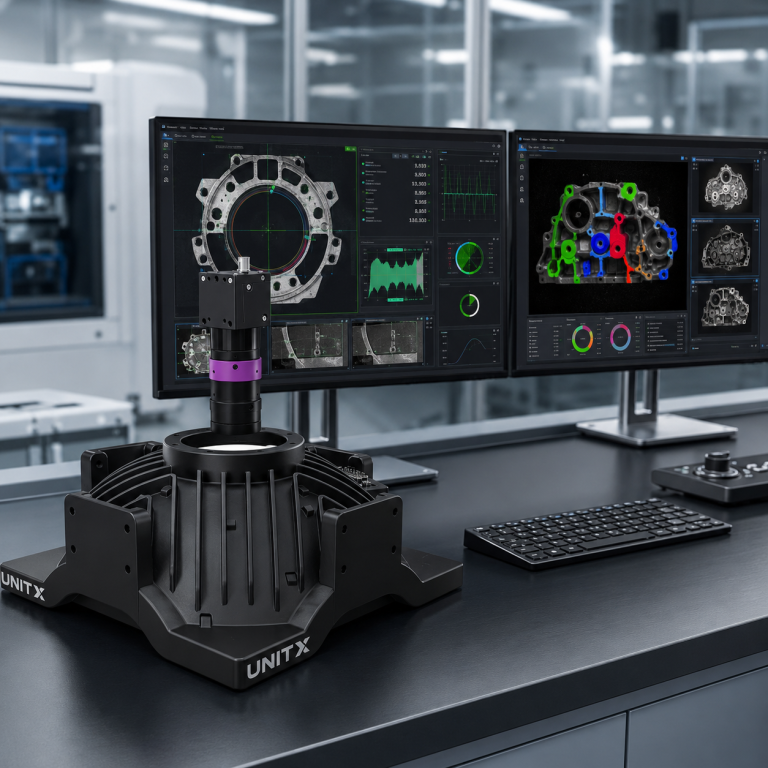
The UnitX OptiX imaging system includes 2.5D depth sensing capability with 3µm Z-repeatability, enabling height profile measurement of complex part geometries alongside 2D surface inspection in a single imaging cycle. This eliminates the need for a separate 3D profiler station in many inspection workflows.
| Dimension Type | Axes Measured | Typical Accuracy | Best Use Case |
| 1D | Single axis (Z or X) | ±0.1–1 mm | Height, gap, linear distance |
| 2D | X and Y (planar) | ±0.005–0.05 mm | Diameter, position, width, angle |
| 2.5D (depth profile) | X, Y + Z height map | ±0.003–0.01 mm (Z) | Weld bead, flatness, height variation |
| 3D (full scan) | Full XYZ point cloud | ±0.001–0.01 mm | Complex geometry, volume, form |
How Dimensional Measurement Works: Edge Detection and Calibration
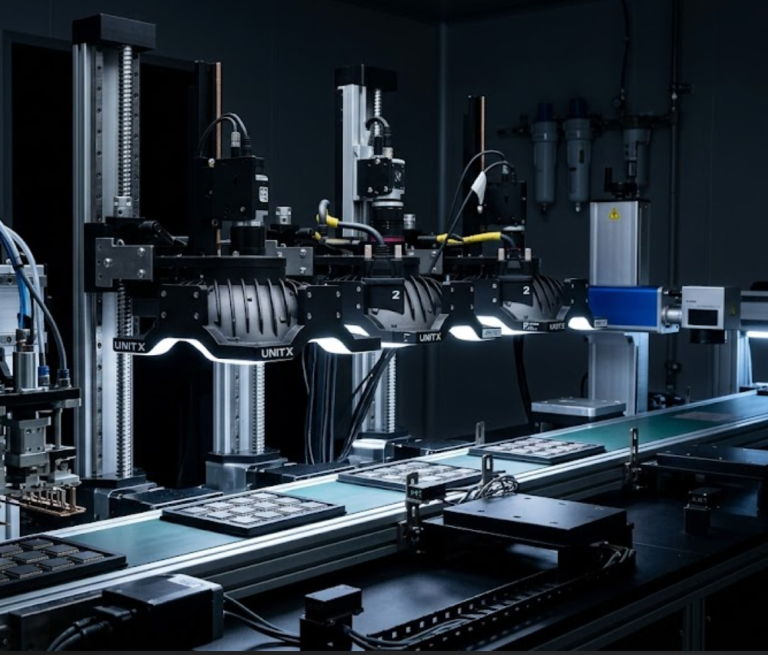
Step 1: Image Capture with Controlled Illumination
Consistent, repeatable illumination is the foundation of reliable dimensional measurement. The lighting strategy is typically chosen to maximize edge contrast: the sharpness of the transition between the part and background in the image. Backlight illumination (light behind the part, camera viewing the silhouette) is the most reliable technique for measuring external dimensions: it creates a perfectly sharp, high-contrast outline where edge detection algorithms can locate boundaries with minimal ambiguity.
For internal dimensions, such as hole diameters, slot widths, and internal radii, backlighting is not always feasible. In these cases, front illumination with careful angle selection (coaxial or low-angle ring lighting) is used instead.
Step 2: Sub-Pixel Edge Detection
Once the image is captured, the software scans across it along predefined measurement paths, locating the position of each edge with sub-pixel precision. The ISO 5725 standard defines measurement accuracy as the combination of trueness (systematic error) and precision (random variation). In machine vision dimensional measurement, calibration determines trueness, while image quality and algorithm stability determine precision (per Quality Magazine, 2024).
Step 3: Calibration — Converting Pixels to Millimeters
Calibration establishes the relationship between pixel coordinates in the image and physical coordinates on the part. A calibration target — a precision artifact with known dimensions (such as a dot grid, checkerboard pattern, or machined reference block) — is imaged under the same conditions as production parts. The vision software fits a mathematical model to the known target dimensions, deriving the pixel-to-millimeter conversion factor and correcting for lens distortion.
Calibration accuracy directly limits measurement trueness. A well-calibrated 2D vision system using a telecentric lens can achieve trueness below 1 µm over a 50 mm FOV. Systems using standard (entocentric) lenses typically achieve 5–20 µm trueness over the same area, depending on the quality of lens distortion correction. Telecentric lenses are preferred for high-accuracy dimensional measurement because they maintain constant magnification regardless of part height variation (a critical advantage when parts are not perfectly flat in the fixture).
AI-Powered Dimensional Inspection: Beyond Fixed Rules
What AI Adds to Dimensional Measurement
Traditional dimensional machine vision systems apply fixed algorithmic logic: find edge A, find edge B, compute distance A-B, and compare it to a tolerance. This approach works well for well-defined geometries with high-contrast edges, but it struggles when:
- Part surfaces have non-uniform reflectivity that shifts apparent edge positions
- Parts have complex or irregular geometries where “the dimension to measure” is not a simple two-point distance
- The inspection task combines dimensional measurement with defect detection (a dimension may be correct, but the surface quality may still be unacceptable)
AI-powered inspection adds a learning layer above the dimensional measurement pipeline. Instead of hard-coded edge detection rules, the model learns the visual patterns that correspond to acceptable vs. unacceptable dimensional conditions from labeled training data. This enables dimensional grading — not just pass/fail — and allows the system to handle natural variation in part appearance without falsely rejecting good parts.
The CorteX AI visual inspection system applies deep learning segmentation to dimensional measurement tasks, enabling pixel-level boundary detection for complex geometries and combining surface defect classification with dimensional compliance verification in a single inspection pass. Training requires as few as 5 images per defect type — significantly reducing setup effort compared to traditional rule-based systems. For customers exploring real-world automotive and battery inspection results, dimensional accuracy data from deployed systems is available in the case study library.
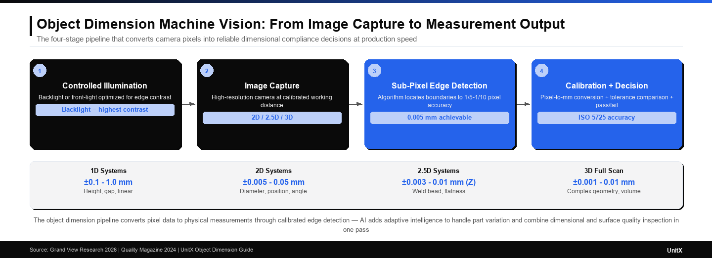
The object dimension machine vision pipeline combines controlled illumination for repeatable edge detection, calibration to convert pixels into physical units, and AI to handle part variation — producing reliable dimensional compliance decisions at production speed.
Common Applications by Industry
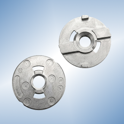
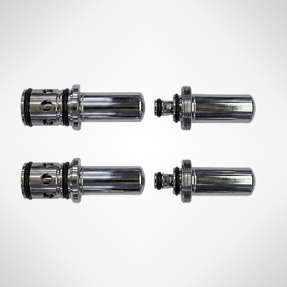
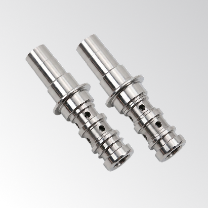
Automotive: Precision Shaft and Component Gauging
Automotive powertrain components — shafts, gears, valve bodies, and connecting rods — require dimensional tolerances in the range of 5–50 µm. Machine vision systems with telecentric lenses and backlight illumination inspect shaft diameters, runout, and key feature positions at 100% inline rates, replacing sampling-based CMM measurement that captures only a fraction of the production output. For EV battery tab geometry inspection — where the CT (current terminal) overhang measurement determines welding quality — 2.5D depth imaging combined with 2D edge detection provides a complete dimensional profile in a single inspection cycle.
Electronics: PCB and Connector Dimensional Verification
Connector pin pitch — the center-to-center spacing between electrical terminals — must meet tolerances as tight as ±0.05 mm to ensure proper mating. Machine vision systems using high-resolution cameras with sub-pixel edge detection achieve the required accuracy at conveyor speeds, replacing sampling inspection with 100% inline gauging. PCB component placement accuracy — verifying that surface-mount components are placed within ±0.1 mm of their target pad center — is another standard machine vision dimensional task across the electronics manufacturing industry.
Medical Devices: Non-Contact Measurement of Delicate Parts
Medical device components — hypodermic needles, stent struts, and catheter dimensions — cannot be touched during measurement without risking contamination or deformation. Machine vision dimensional measurement with backlight illumination provides non-contact gauging of outer diameter, wall thickness, and taper angle with µm-level accuracy. The requirement for 100% dimensional inspection (not sampling) of implantable components drives the adoption of inline machine vision over traditional touch-probe CMM approaches.
If you are evaluating object dimension machine vision for a specific application — whether automotive shaft gauging, EV battery tab measurement, or connector pitch inspection — contact UnitX to discuss system requirements, expected accuracy, and how AI-powered inspection can combine dimensional verification with surface defect detection in a single pass.
Frequently Asked Questions
What is an object dimension machine vision system?
It is an automated inspection system that uses cameras, controlled illumination, and software to measure the physical size, shape, and geometry of manufactured parts — replacing manual gauging tools like calipers and micrometers. The system converts pixel-level image data into physical measurements (mm or µm) and compares them to design tolerances to determine pass/fail or dimensional grades for each part.
What is the difference between 2D and 3D machine vision dimensional measurement?
2D systems measure dimensions in the horizontal and vertical image plane (X and Y) — ideal for outer diameter, width, length, and position measurements visible from a single camera angle. 3D systems add the Z axis (depth), enabling measurement of height variation, weld bead profiles, flatness, and volume. 3D systems are more complex and expensive but are necessary when the geometry being measured varies significantly along the Z axis.
How accurate is machine vision dimensional measurement?
Accuracy depends on system design, calibration quality, and lens type. Well-designed 2D systems with telecentric lenses and sub-pixel edge detection can achieve trueness of 1–5 µm over a 50 mm field of view. Standard entocentric lens systems typically achieve 5–20 µm trueness. 3D systems range from ±0.01 mm (high-end structured light) to ±0.1 mm (lower-cost depth sensors). The ISO 5725 standard defines trueness and precision as separate components of total measurement accuracy.
What is sub-pixel edge detection in machine vision?
Sub-pixel edge detection is an algorithm technique that locates the position of a part boundary to a fraction of the pixel spacing — typically 1/5 to 1/10 of a pixel. Instead of assigning the edge to the nearest pixel, the algorithm fits a mathematical model (e.g., Gaussian or centroid) to the brightness gradient profile across adjacent pixels, interpolating the edge position with sub-pixel precision. This allows a camera with 0.05 mm/pixel resolution to achieve edge detection accuracy of 0.005–0.01 mm — a critical capability for tight-tolerance dimensional inspection.
How does AI improve object dimension machine vision?
AI adds adaptive learning to dimensional measurement. Instead of relying on hard-coded edge detection rules that can fail when surface reflectivity varies or part geometry is complex, AI models learn the visual patterns of correctly dimensioned and out-of-tolerance parts from training data. This enables the system to handle real-world variation without excessive false rejections, combine dimensional verification with surface defect classification in a single inspection pass, and continuously improve accuracy as more production data becomes available — capabilities that traditional rule-based systems cannot match. Explore UnitX’s AI visual inspection solutions that combine AI-powered dimensional measurement with surface defect detection for comprehensive inline quality control.