Before a camera can inspect a part, measure a dimension, or detect a defect, the engineering team must answer a deceptively fundamental question: how much of the scene does the camera actually see? That answer is the field of view, and getting it wrong, even slightly, is enough to cause an entire inspection system to fail. Objects may fall outside the camera frame. Defects at the edge of the part may appear blurry. Resolution may be too coarse to detect the minimum feature size. Field of view (FOV) is one of the first and most consequential design decisions in any machine vision system. This guide explains what FOV means, how to calculate it, and why it directly determines whether your AI visual inspection system can perform effectively.
Key Takeaways
- Field of view (FOV) is the physical area captured by a machine vision camera at a given working distance, defined by sensor size, lens focal length, and the distance from the camera to the part.
- FOV and resolution have a direct trade-off: a wider FOV means fewer pixels per millimeter, reducing the system’s ability to detect small features.
- For industrial AI visual inspection, the FOV must be large enough to capture the entire part and narrow enough to resolve the smallest defect, a constraint that simultaneously drives lens selection, camera resolution, and system layout.
What Is the Field of View in Machine Vision?
The Definition
Field of view in machine vision is the physical area, measured in millimeters or inches, that a camera-lens combination can capture and project onto the image sensor at a specific working distance. It defines the observable “window” through which the inspection system sees the world.
FOV is typically expressed in two dimensions: horizontal (H-FOV) and vertical (V-FOV). If the camera’s H-FOV is 120 mm and the part being inspected is 115 mm wide, the part fits within the camera’s view with 2.5 mm of margin on each side (5 mm total). If the part is 125 mm wide, it falls outside the FOV, and portions of the part are not imaged at all.
The field of view is not a fixed property of a camera or lens alone. It is a function of three variables working together:
- Sensor size — the physical dimensions of the image sensor’s active area
- Lens focal length — the optical distance that determines the magnification ratio
- Working distance — the physical distance from the front of the lens to the inspected surface
FOV vs. Depth of Field: A Common Confusion
FOV (field of view) describes the lateral area captured — how wide and tall the image window is. Depth of field (DOF) describes how much variation in depth (Z-axis distance) can be tolerated while still producing a sharp image. A camera focused at a 200 mm working distance with a 10 mm DOF will produce sharp images of parts that range from 195 mm to 205 mm from the lens, anything outside that range will appear out of focus. Both FOV and DOF are critical design parameters, but they are independent: you can have a wide FOV with shallow DOF, or a narrow FOV with deep DOF, depending on lens and aperture selection.
How to Calculate Field of View
The Core Formula
The standard FOV calculation for industrial machine vision is based on the geometric optics relationship between sensor size, focal length, and working distance—derived from the mathematics of similar triangles in the optical path:
- H-FOV = (Sensor Width × Working Distance) / Focal Length
- V-FOV = (Sensor Height × Working Distance) / Focal Length
Where sensor width and height are the physical dimensions of the image sensor (in millimeters), working distance is the distance from the lens to the part surface (in millimeters), and focal length is the lens focal length (in millimeters).
Worked Example: Connector Inspection
A quality engineer needs to inspect electrical connectors that are 80 mm wide × 60 mm tall. The system design requires a 300 mm working distance to allow room for fixturing and part handling. The camera has a 2/3″ sensor (8.8 mm × 6.6 mm). What focal length lens is required?
Rearranging the formula:
Focal Length = (Sensor Width × Working Distance) / Required H-FOV
Focal Length = (8.8 mm × 300 mm) / 90 mm = 29.3 mm
The nearest standard focal length would be 25 mm (slightly wider FOV) or 35 mm (slightly narrower).
- At 25 mm, the actual H-FOV becomes: (8.8 × 300) / 25 = 105.6 mm, providing sufficient coverage with comfortable margin.
- At 35 mm: (8.8 × 300) / 35 = 75.4 mm, which is too narrow, the connector would not fully fit within the frame.
| Focal Length | H-FOV (mm) | V-FOV (mm) | Part (80×60mm) Fits? |
| 16 mm | 165 mm | 123.8 mm | Yes: very wide, low resolution |
| 25 mm | 105.6 mm | 79.2 mm | Yes: good fit with margin |
| 35 mm | 75.4 mm | 56.6 mm | No:part too wide |
| 50 mm | 52.8 mm | 39.6 mm | No : significantly undersized |
Note: This calculation assumes a standard 2/3″ sensor (8.8 × 6.6 mm) at a 300 mm working distance, applying fundamental optical principles.
FOV and Resolution: The Core Trade-Off
Why Wider FOV Means Less Detail
Field of view and spatial resolution have an inverse relationship in any fixed-sensor system. A camera with 5 megapixels (5,000,000 pixels) produces roughly 2,590 × 1,940 pixels. If the H-FOV is 100 mm, each pixel covers 100 mm ÷ 2,590 pixels = 0.039 mm per pixel. If the H-FOV is expanded to 200 mm, each pixel covers 200 ÷ 2,590 = 0.077 mm per pixel. The minimum detectable feature size doubles, small defects that were visible at a 100 mm FOV become undetectable at 200 mm FOV with the same camera.
A general design rule is that the minimum detectable feature should span at least 2 pixels in the image, and ideally 3 – 4 pixels for reliable AI classification with consistent results. If you need to detect a 0.1 mm scratch on a part that is 150 mm wide, the calculation is:
- Required pixel density: 0.1 mm ÷ 3 pixels = 0.033 mm/pixel
- Required pixel count across H-FOV: 150 mm ÷ 0.033 mm/pixel = 4,545 pixels
- Minimum camera resolution: 4,545 × (V-FOV equivalent) pixels, approximately 20+ megapixels for a realistic part geometry
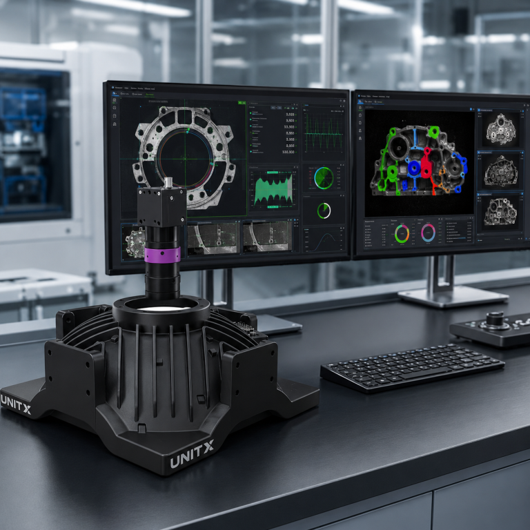
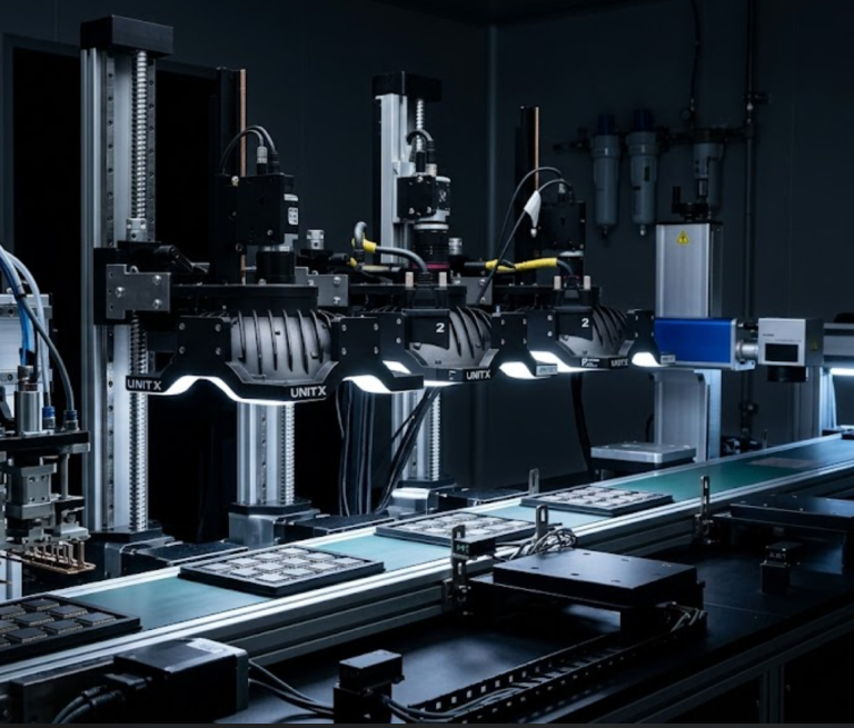
This is exactly why high-resolution imaging matters in production inspection. UnitX’s CorteX AI visual inspection system supports up to 50 MP single-image capture — enabling wide FOV coverage of large parts without sacrificing the pixel density needed to detect sub-millimeter defects. When combined with the OptiX multi-angle imaging system, which has a maximum configurable FOV of 500 mm (modular), manufacturers can inspect large components with the resolution previously achievable only on small parts.
Common Sensor Sizes and Their FOV Characteristics
Standard Sensor Formats in Industrial Machine Vision
Sensor size is specified in “inch format”, a historical designation that does not directly correspond to the physical diagonal of the sensor but serves a standard reference. The actual physical dimensions are what matter for FOV calculations.
| Sensor Format | Width (mm) | Height (mm) | Typical Use |
| 1/4″ | 3.2 | 2.4 | Compact/miniature inspection |
| 1/3″ | 4.8 | 3.6 | General industrial detection |
| 1/2″ | 6.4 | 4.8 | High-precision measurement, 5 MP |
| 2/3″ | 8.8 | 6.6 | High-resolution inspection, 10 – 20 MP |
| 1″ | 12.8 | 9.6 | Ultra-high precision, 3D vision |
Larger sensors provide a wider FOV at the same focal length and working distance, or equivalently, allow the use of a longer focal length (resulting in less distortion and better edge sharpness) while maintaining the same FOV. This is why high-performance industrial inspection systems increasingly use large-format sensors paired with high-resolution AI inference.
FOV in Practice: Multi-Camera and Modular FOV Systems
When One Camera Is Not Enough
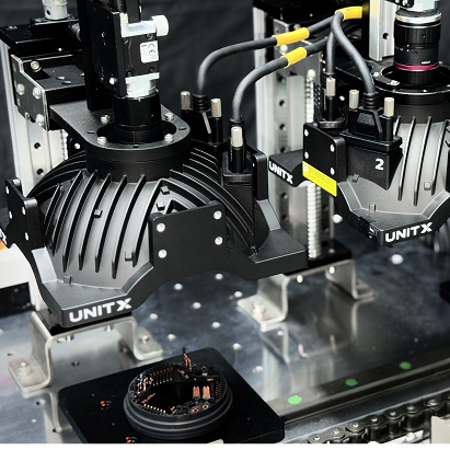
For those large parts, such as automotive body panels, battery modules, or PCBAs over 300 mm in any dimension, a single camera with sufficient pixel density to detect sub-millimeter defects across the entire surface is often physically impossible or cost-prohibitive. The practical solution is a multi-camera array, where each camera covers a sub-region of the total inspection area with sufficient resolution, and the AI inference system processes all camera feeds simultaneously.
Coordinating FOV across multiple cameras requires careful calibration to ensure there are no gaps between adjacent camera fields and no excessive overlap that would waste pixel budget. The UnitX OptiX imaging system is designed with modularity to address this: OptiX units can be arranged in arrays to cover up to a 500 mm total FOV, with the CorteX system managing the multi-camera inference pipeline. This modular FOV approach is documented in UnitX deployments for full-surface inspection of EV battery top covers and automotive transmission components, where no single camera configuration could provide adequate coverage at the required resolution. View customer case studies for concrete FOV and resolution configurations used in production.
FOV, resolution, and working distance form an interconnected triangle: changing any one variable forces a trade-off in the other two. Understanding this relationship is the foundation of every machine vision system design decision.
FOV Considerations for AI Visual Inspection
How FOV Affects AI Model Training and Performance
An AI inspection model is trained on images captured at a specific FOV and resolution. If the FOV changes after deployment, due to camera repositioning or shifts in working distance caused by fixturing wear, the scale of features in the image changes relative to what the model was trained on. A scratch that occupied 5 pixels in the training dataset may now span only 3 pixels, and the model may fail to classify it correctly.
This is why maintaining a consistent FOV in production is not just an optical engineering concern, it directly affects the reliability of the AI inference model. Well-designed AI visual inspection systems include camera calibration verification as part of the startup routine, and some advanced systems use continuous spatial calibration to detect and compensate for FOV drift without interrupting production.
If you are designing a machine vision system for a new inspection application and need to determine the right FOV, sensor, and lens combination for your specific part size and defect requirements, contact the UnitX engineering team to discuss optical system design as part of a complete AI visual inspection solution.
Frequently Asked Questions
What is field of view (FOV) in machine vision?
FOV is the physical area measured in millimeters or inches, that a machine vision camera and lens combination can capture at a specific working distance. It defines how much of a part or scene is visible to the camera. FOV is determined by three variables: sensor size, lens focal length, and working distance. Changing any of these will change the FOV.
How do I calculate the field of view for a machine vision camera?
Use the formula: FOV = (Sensor Size × Working Distance) / Focal Length. For a camera with a 1/2″ sensor (6.4 mm wide × 4.8 mm tall), a 25 mm lens, and 300 mm working distance:
- H-FOV = (6.4 × 300) / 25 = 76.8 mm
- V-FOV = (4.8 × 300) / 25 = 57.6 mm
The part must fit within these dimensions to be fully captured in a single frame.
What is the difference between FOV and resolution in machine vision?
FOV is the physical area captured, while resolution is the pixel density within that area. They are inversely related for a fixed-sensor camera: doubling the FOV halves the number of pixels per millimeter. For defect detection, you need sufficient pixel density to resolve the smallest defect, which sets an upper limit on the FOV for a given camera resolution.
How does working distance affect field of view?
Increasing working distance increases FOV proportionally: if you double the working distance, the FOV also doubles. This reduces image resolution (fewer pixels per millimeter) and typically requires brighter illumination to maintain adequate image exposure. Decreasing working distance narrows the FOV but increases resolution and depth of field sensitivity.
What FOV should I use for AI defect detection?
The FOV should be large enough to capture the entire part with a few millimeters of margin on each side, and narrow enough that the smallest defect you need to detect spans at least 2 – 3 pixels in the image. If a single camera cannot satisfy both constraints, a multi-camera array with modular FOV coverage is the engineering solution. Systems like UnitX’s OptiX support up to 500 mm modular FOV with AI inference across all camera channels, enabling large-part inspection at micro-defect resolution.