Pick up any polished metal part, hold it under an overhead ring light, and watch the reflection bloom into a white hotspot that obliterates every surface feature you are trying to inspect. That blinding specular reflection — the curse of every machine vision engineer working with reflective surfaces — is precisely what coaxial illumination was designed to exploit rather than fight. This article explains how on-axis coaxial lighting works, where it outperforms other illumination techniques, and where its fundamental geometry becomes a limitation.
Key Takeaways
- Coaxial (on-axis) lighting directs light along the same optical axis as the camera using a beamsplitter, so flat reflective surfaces return light directly to the sensor while recessed features scatter it away — appearing dark.
- This geometry makes coaxial light uniquely effective for inspecting highly reflective, flat surfaces: PCBAs, polished metal stampings, wafers, glass panels, and mirror-finish components.
- The beamsplitter inherently wastes 75% of available light intensity (50% on the way in, 50% on the way back), making coaxial lighting less suitable for high-speed inspection where exposure time is constrained.
- Coaxial light is a subcategory of bright field illumination; its key differentiator from ring and bar lights is the zero-angle, axis-aligned light path enabled by the beamsplitter optic.
- In software-defined imaging systems, combining multiple independently addressable light channels — including coaxial — enables adaptive lighting that selects the optimal technique per part type without hardware changes.
The Physics of Coaxial Illumination
How a Beamsplitter Creates On-Axis Lighting
In a standard bright field setup, a ring light or bar light is positioned at an angle relative to the camera’s optical axis. On a flat reflective surface, the angle of reflection equals the angle of incidence — so the specular highlight appears offset, creating uneven brightness that varies with surface orientation and finish.
Coaxial illumination eliminates this issue by inserting a beamsplitter (a partially reflective, partially transmissive glass plate) into the optical path between the lens and the sensor. The light source is positioned to the side, at 90° to the optical axis. The beamsplitter reflects this light downward along the same axis as the camera’s line of sight. When this on-axis light hits a flat, mirror-like surface, it reflects directly back along the same axis — passing through the beamsplitter and into the sensor. The surface appears uniformly bright.
Any feature that is not perfectly flat — a recess, raised bump, crack, engraved character, or surface defect — scatters light off-axis. These features do not return light to the sensor and therefore appear dark against the bright background. This contrast — dark features on a bright field — is what makes coaxial lighting the standard choice for PCB inspection, wafer surface metrology, and engraved mark verification.
The Beamsplitter’s Intensity Penalty
The beamsplitter’s optical properties introduce an unavoidable efficiency loss. A standard 50/50 beamsplitter reflects 50% of incident light and transmits the other 50%. In a coaxial setup, light passes through the beamsplitter twice: once on the way to the surface (losing 50%) and once on the return path to the sensor (losing another 50% of the remaining light). The result is that only about 25% of the emitted light reaches the sensor — a fourfold reduction compared to direct illumination.
This is a critical constraint in high-speed inspection. At 1,200 parts per minute, with roughly a 1 ms cycle time per frame, losing 75% of available light tradeoffs: shorter exposure times (increasing noise) or higher-intensity light sources (increasing power, heat, and cost). As documented in Vision Systems Design’s coaxial illumination analysis: “only a maximum of 25%” of the available light intensity passes through the full beamsplitter path — making this a fundamental physical constraint, not an engineering choice.
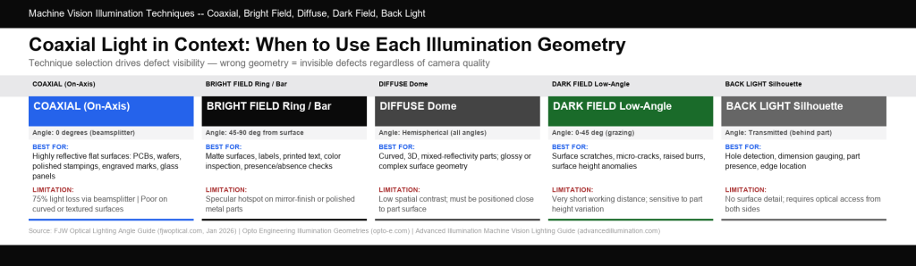
Illumination technique comparison: coaxial (on-axis), bright-field ring, and dark-field lighting. Each geometry produces different contrast signatures on flat, recessed, and raised surface features.
Coaxial vs. Other Machine Vision Lighting Techniques
Comparing Illumination Geometries
| Technique | Light Angle | Best For | Limitation |
| Coaxial (On-Axis) | 0° (same axis as camera) | Reflective flat surfaces, PCB, wafers, engravings | 75% light loss; poor on curved/textured surfaces |
| Bright Field Ring / Bar | 45–90° from surface | Matte surfaces, labels, color inspection | Specular hotspot on reflective surfaces |
| Diffuse Dome | Hemispherical (all angles) | Curved, mixed-reflectivity, complex 3D parts | Low spatial contrast; must be close to part |
| Dark Field | 0–45° from surface (grazing) | Surface scratches, micro-cracks, raised features | Very short working distance; sensitive to part height |
| Back Light | Transmitted (from behind) | Silhouette, dimension gauging, holes | No surface detail; requires part access from both sides |
When Coaxial Outperforms Dark Field
The comparison that confuses most engineers encountering it for the first time is coaxial vs. dark-field lighting for reflective surface inspection. Both can reveal surface features on metallic parts, but through opposite mechanisms:
- Dark field — Light grazes the surface at low angles. Flat areas scatter light away from the camera (appearing dark), while features with height discontinuities (scratches, burrs, raised contamination) scatter light toward the camera (appearing bright against a dark background).
- Coaxial — Light is directed along the optical axis. Flat areas reflect light directly back to the camera (appearing bright), while recessed or angled features scatter light away (appearing dark against a bright background).
In a coaxial setup, non-flat features scatter light outside the lens’s maximum acceptance angle, causing them to appear distinctly dark against a bright background. The choice between coaxial and dark field ultimately depends on which contrast polarity your detection algorithm performs better on — and whether you need to isolate raised or recessed features.
Primary Applications of Coaxial Lighting in Industrial Inspection
PCBA and Electronics Inspection
Printed circuit board assemblies (PCBAs) present a uniquely challenging inspection surface due to their mixed reflectivity: shiny solder joints, bare copper pads, matte solder mask, and dark component bodies. Coaxial lighting creates strong contrast between the flat, reflective metallic areas (which return light directly to the sensor and appear bright) and the non-reflective surrounding mask (which appears dark). Defects such as missing components, insufficient solder paste, or pad contamination scatter the on-axis light, making them immediately visible as sharp, dark anomalies.
Crucially, the “straight-down” geometry of coaxial light solves the 3D shadowing problem inherent to populated boards. While standard ring lights cast angular light that creates harsh shadows behind tall component bodies, coaxial illumination bypasses these obstructions. This shadow-free consistency across the board is vital for maintaining the stable contrast required for reliable automated defect detection.
Semiconductor Wafer Inspection
Silicon wafers are optically flat and mirror-smooth, making them ideal candidates for coaxial illumination. The on-axis geometry returns maximum light from the undamaged wafer surface while die boundaries, scratches, particles, and etch non-uniformities appear with strong contrast. The requirement for high spatial uniformity across the wafer surface — which directly impacts false rejection rate in high-value semiconductor production — makes the uniform bright field of coaxial light preferable to any directional alternative.
Engraved and Laser-Marked Characters
Reading laser-engraved serial numbers, part codes, and date stamps on metallic surfaces is a canonical coaxial application. The engraved or marked area scatters light off-axis and appears dark, while the unmarked metal surface reflects directly to the sensor. The result is maximum contrast between the mark and the background without requiring the part to have any inherent optical distinction (such as color or texture) between the two.
Glass and Transparent Component Inspection
Glass surfaces present unique inspection challenges: partial reflectivity, surface scratches visible only at specific angles, and subsurface defects that require light to penetrate the material. Research published in Vision Systems Design found that for translucent materials exhibiting subsurface scattering, “using coaxial illumination can result in a significant increase in image texture, which greatly benefits 3D height reconstruction” compared to tube lighting. This is because the on-axis geometry maximizes the direct first-surface reflection that carries surface detail information.
Practical Setup Considerations
Working Distance and Optical Path Effects
Inserting a beamsplitter into the optical path between the lens and the scene has two effects beyond the intensity penalty: it introduces a small shift in the working distance (the plane of sharpest focus moves slightly) and a minor reduction in optical image quality due to the additional glass element. For precision measurement applications, this shift must be accounted for in system calibration. For standard inspection tasks, the effect is typically within the len’s depth of field and can be ignored.
Coaxial lighting also performs best when the working distance is carefully optimized. As a fundamental rule of optics, increasing the distance between the light source and the target enhances the system’s ability to reject unwanted diffused light. This strict rejection of off-axis scattering is what produces the crisp, high-contrast image definition required for reliable automated inspection.
Integration with Multi-Channel Lighting Systems
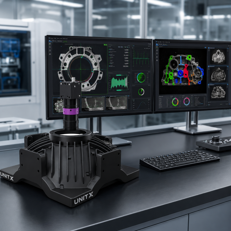
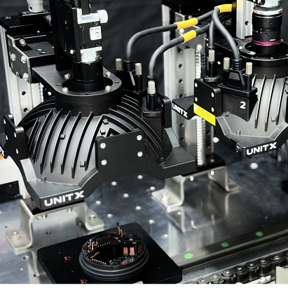
Modern AI visual inspection platforms increasingly deploy multi-channel, software-defined illumination rather than fixed, single-technique lighting. OptiX — UnitX’s imaging front-end — features 32 independently controllable light channels that can combine coaxial, multi-angle, and wavelength-varied illumination in a single imaging pass. This architecture eliminates the need for hardware reconfiguration when switching lighting techniques between product families and enables the system to adaptively select the illumination condition that maximizes defect contrast for each specific defect type.
For flat, reflective surfaces like battery cell top caps, connector terminals, or stamped metal parts, this means coaxial lighting can be used for one image capture while dark-field illumination is used for a second capture within the same inspection cycle — each revealing defect types invisible to the other. Teams evaluating multi-modal lighting for inline inspection can explore how OptiX software-defined imaging handles this. For a broader overview of AI inspection system architecture, UnitX customer case studies illustrate deployment patterns across automotive, battery, and semiconductor applications.
Coaxial Light: When Not to Use It
Curved or Irregular Surfaces
Coaxial light’s core property — that flat areas appear bright and angled areas appear dark — becomes a liability on curved parts. A spherical bearing surface, a cylindrical shaft, or a convex component body will reflect coaxial light away from the camera at all positions except the very center (directly normal to the surface). The result is a dark, featureless image with a single bright spot at the surface normal — the opposite of what is useful for inspection. For curved parts, dome lighting (diffuse hemispherical) is the correct choice.
Highly Textured Surfaces
Coarsely textured surfaces (cast metal, rough plastic, fabric) scatter coaxial light diffusely in all directions. The on-axis geometry provides no contrast advantage over a standard bright-field ring light on these surfaces, and the 75% intensity penalty becomes an unnecessary cost. Bright-field ring or bar lights, or dark-field lighting for specific defect types, are more appropriate choices.
When Feature Contrast Requires Shadow Formation
Some inspection tasks depend on shadowing to reveal features — such as height differences, misaligned components, or topographic variation. Shadow formation requires a directional, off-axis light source. Coaxial light, being on-axis, cannot cast shadows. For these applications, angled bright-field or structured-light illumination is required.
Frequently Asked Questions
What is the difference between coaxial and diffuse dome lighting?
Both are bright-field techniques, but their light geometries are opposite. Coaxial light illuminates from a single direction — precisely on-axis — creating strong contrast between flat reflectors (bright) and off-normal surfaces (dark). Diffuse dome lighting illuminates from all directions simultaneously, creating a uniform “cloudy sky” effect that eliminates shadows and minimizes specular hotspots. Coaxial lighting is ideal for flat, reflective surfaces where directional contrast matters; dome lighting is ideal for curved or 3D parts where uniform, shadow-free illumination is needed.
Why does coaxial lighting lose 75% of its light intensity?
The beamsplitter is a partially transmissive, partially reflective optic — typically with a 50/50 split. Light from the source hits the beamsplitter, and 50% is reflected down to the part. Of the light returned from the part, only 50% passes through the beamsplitter to the camera. Since 0.5 × 0.5 = 0.25, only 25% of the source light reaches the sensor. High-intensity LED sources (which can be 100× brighter than traditional lighting, as in OptiX’s illumination architecture) can mitigate this penalty but cannot eliminate it. The 75% loss is inherent to any transmissive beamsplitter geometry.
Can coaxial lighting be used with color cameras?
Yes. The beamsplitter is optically neutral across the visible spectrum — it transmits and reflects light across the full visible range without significant wavelength discrimination. White-light coaxial illumination with a color camera is standard practice in PCB inspection and label verification applications where both reflectivity contrast and color information are needed. For UV or near-infrared wavelengths, specialized beamsplitters with appropriate coating properties are required.
What is “telecentric coaxial” lighting and when is it used?
Telecentric coaxial illumination combines a telecentric lens (which images objects with zero parallax — all rays are parallel regardless of object position) with built-in coaxial illumination. This ensures that both imaging and illumination are perfectly on-axis across the entire field of view, eliminating edge darkening and perspective effects that can occur with standard coaxial setups on wide fields. Telecentric coaxial lighting is preferred for dimensional measurement on flat, reflective parts where accuracy across the full field of view is critical — common in semiconductor packaging and precision connector inspection.
How does coaxial light compare to structured light for surface inspection?
Coaxial light is a 2D illumination technique: it enhances image contrast for 2D surface feature detection (defects, marks, text). Structured light is a 3D technique: it projects a known pattern onto the surface and uses its deformation to compute depth maps. They address different problems. Structured light reveals surface topography; coaxial does not. Coaxial provides shadow-free, uniform illumination that makes flat-surface features highly visible; while structured light systems focus on depth reconstruction. In practice, advanced inspection platforms often combine both — coaxial or multi-angle 2D imaging for surface defect detection, alongside structured light or depth sensing for dimensional inspection.