Introduction: Securing the Engine’s Critical Link
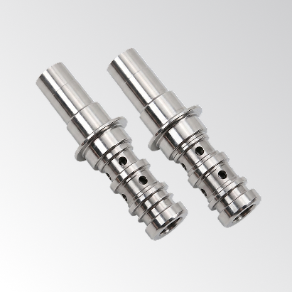
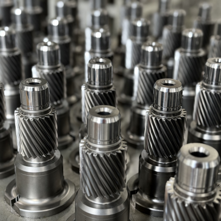
The Connecting Rod is the unsung hero of the internal combustion engine. It links the piston to the crankshaft, converting linear explosions into rotational force. It operates under immense stress, heat, and speed.
Because of this harsh operating environment, there is zero margin for error. A microscopic crack, a burr, or an area of “whitening” (exposed substrate) can propagate under stress, leading to a snapped rod and catastrophic engine failure.
For our client, relying on manual inspection was no longer an option. It was costly, inconsistent, and left the door open for “after-sales problems”—a polite term for blown engines and massive warranty claims.
The Challenge: Surface and Structural Integrity
The project goal was to automate the inspection of the entire rod to ensure engine safety and mechanical performance.
The Defect Landscape:
The system needed to detect a mix of cosmetic and structural issues:
- Surface Defects: Scratches, dirt, press marks, and air bubbles.
- Manufacturing Defects: Short welds, abnormal stamping marks, excess/missing material.
- Structural Indicators: Cracks and “Whitening” (exposed metal indicating coating failure).
The geometry of a connecting rod is complex, with curves and oil holes that hide defects from standard top-down cameras.
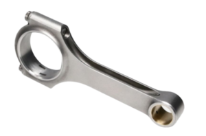
Connecting rods require 360° inspection to detect defects that could lead to catastrophic engine failure.
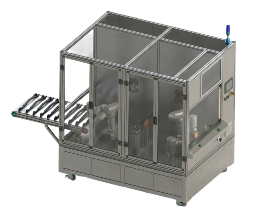
The Solution: Robotic Manipulation for 360° Views
UnitX deployed a Robotic Dual-Workstation System designed for total coverage.
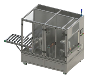
The UnitX cell uses a robot to manipulate the connecting rod in front of the fixed OptiX.
How it Works:
-
- Robotic Manipulation: Uses a “part-to-sensor” workflow for stable, repeatable positioning.
- Fixed OptiX Imaging: Stationary sensors capture vibration-free, high-resolution images.
- 360° Coverage: Coordinated robotic rotation ensures a full-surface inspection of every part.
- MES Integration: Automatic data and statistics upload for end-to-end traceability.
Results: Clarity and Consistency
The system brought high-resolution clarity to defects that were previously subjective.
1. High-Clarity Defect Capture
The system proved effective at capturing difficult defects like “Exposed Substrate” (whitening), which can be hard to distinguish from reflections on shiny metal.
2. Safety-First Thresholds
- False Acceptance Rate (FA): ≤ 1%.
- By strictly maintaining a low False Accept Rate, the system ensures that no defective components ever make it into an engine assembly.
3. Optimized Cycle Time
- Cycle Time: ≤ 15 seconds per piece.
- Considering the robot must pick up, rotate, and present the part for a 360° scan, a 15-second cycle time represents a highly efficient process for such a heavy, complex component.
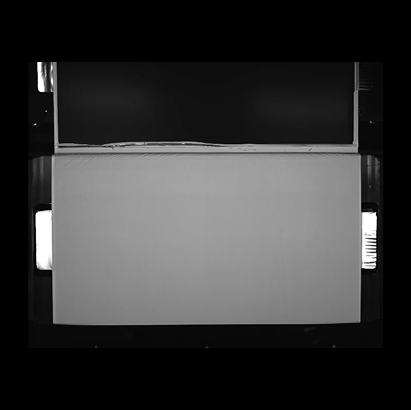
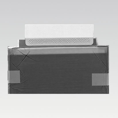
Defect Visualization
The images below show the system’s ability to detect “Exposed Substrate”—a critical defect where the surface coating has failed, exposing the raw metal beneath.
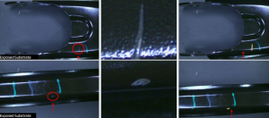
UnitX AI clearly identifies areas of exposed substrate and surface whitening.
Conclusion
In powertrain manufacturing, a “small” defect is just a big failure waiting to happen. UnitX’s robotic inspection solution removes the variability of human inspection, ensuring that every connecting rod is strong enough to handle the pressure.
Ensure your powertrain components are road-ready.
Contact UnitX to automate your critical component inspection.