A flat field correction machine vision system removes blurry spots and bright patches from every image in seconds. Many teams struggle when uneven lighting or dust on a lens ruins a critical photo. With a flat field correction machine vision system, they see sharp, even results right away. This tool helps them spot details faster and work with clear images every time.
Key Takeaways
- Flat-field correction removes uneven brightness and sensor noise to produce clear, uniform images in machine vision systems.
- Proper calibration with uniform lighting and stable camera settings is essential for accurate correction and consistent image quality.
- Real-time correction uses stored calibration data to fix images instantly, supporting fast and reliable inspections without slowing down processing.
- This correction improves defect detection accuracy, reduces manual adjustments, and boosts workflow efficiency in industries like manufacturing and electronics.
- Regular calibration and understanding the imaging setup help maintain correction accuracy and ensure lasting success in machine vision applications.
Image Issues
Causes in Machine Vision
Many problems can affect the quality of an image in a machine vision system. These problems often come from the environment, equipment, or setup. Some common causes include:
- Vibration shakes the camera or lighting, which leads to blurry images and makes correction more difficult.
- Improper or uneven lighting creates bright spots or dark areas, making it hard for the system to capture a clear image.
- Dust, water, or debris on the lens scatters light and lowers image clarity, which increases the need for correction.
- Mechanical misalignment of the camera or lighting, often caused by impact or loose fixtures, results in uneven images that require correction.
- Electrical issues, such as loose cables or network problems, can cause sudden changes in image quality.
- Changes in the surface of the part being inspected, like different reflectivity, can affect how the image appears and may need correction.
- Incorrect exposure time, especially if too long, can cause motion blur and reduce the effectiveness of correction.
Lighting plays a key role in machine vision. Proper lighting improves image clarity and contrast, making correction easier. Tailored lighting solutions help focus on important areas and support accurate correction.
Effects on Quality
Image quality problems in machine vision systems can lower the accuracy of defect detection and slow down production. The table below shows how sensor pixel size and lighting inconsistencies affect image quality and correction:
| Aspect | Effect of Smaller Pixels | Effect of Larger Pixels | Additional Techniques and Considerations |
|---|---|---|---|
| Pixel Size | Increases spatial resolution, enabling detection of finer details | Improves sensitivity by capturing more light | Pixel binning can combine pixels to enhance sensitivity but reduces resolution |
| Sensitivity | Reduced due to fewer photons collected per pixel | Increased due to larger photon collection | Proper lighting and high-quality lenses improve image clarity |
| Resolution | Higher spatial resolution, better detail detection | Lower spatial resolution due to larger pixel size | Nyquist criterion requires at least two pixels per smallest feature to avoid aliasing |
Lighting inconsistencies can cause over-exposure or under-exposure. Over-exposure saturates pixels, making correction less effective and hiding important details. Under-exposure can hide features, which reduces the reliability of correction. Environmental factors like heat or vibration also increase noise and blur, making correction more challenging.
Automated inspection systems with high-quality image capture and proper correction can achieve defect detection rates above 99%. Preprocessing steps, such as noise reduction and contrast adjustment, improve correction and help the system find defects more accurately. However, if the original image is too degraded, even the best correction cannot restore lost information. High-quality image capture and correction remain essential for reliable machine vision performance.
Flat Field Correction Machine Vision System
What Is Flat-Field Correction
Flat-field correction is a process that improves the quality of a two-dimensional image in a machine vision system. This method removes unwanted patterns and uneven brightness caused by the image sensor, lens, or lighting. Each pixel in an image sensor can have a different sensitivity. Some pixels may react more to light, while others react less. This difference creates nonuniformity in the final image, even if the lighting looks even to the human eye.
Flat-field correction uses a special calibration process. The system first captures a dark image with no light. This step helps find the baseline noise for each pixel. Next, the system takes a picture of a clean, white surface with even lighting. This image shows how each pixel responds to light. The flat field correction machine vision system uses these two images to create a correction matrix. This matrix adjusts every new image, so the output looks even and clear.
The correction process works best when the camera, lens, and lighting stay the same during calibration and image capture. If anything changes, the system needs a new calibration. Flat-field correction removes fixed-pattern noise and corrects for vignetting, dust, and other optical issues. This process ensures that a uniform input produces a uniform output, which is important for accurate machine vision tasks.
Note: Flat-field correction is a standard step in many digital imaging devices, from cameras to telescopes. It helps every pixel show the true scene, not just the sensor’s quirks.
Why It Matters
Flat-field correction plays a key role in machine vision. Without it, images can show bright spots, dark corners, or strange patterns. These problems make it hard for the system to find defects or measure parts correctly. Nonuniformity correction fixes these issues by making the image look even across the whole field of view.
Nonuniformity correction addresses both pixel sensitivity differences and lighting problems. It removes fixed-pattern noise, which often appears as stripes or spots in the image. This noise can come from temperature changes or differences in the image sensor. The correction also handles lens shading, which causes the edges of the image to look darker than the center.
A flat field correction machine vision system uses nonuniformity correction to improve image uniformity and clarity. This step is critical for industries that need high accuracy, such as electronics, manufacturing, and medical imaging. For example, in visual odometry or object tracking, even small errors in image uniformity can cause big mistakes.
Researchers have shown that flat-field correction leads to better image quality in machine vision workflows. When the system applies nonuniformity correction, it can spot tiny defects and measure parts more reliably. The correction also reduces the need for manual adjustments, saving time and effort.
The table below shows how nonuniformity correction improves image quality:
| Problem Before Correction | Result After Nonuniformity Correction |
|---|---|
| Bright or dark patches | Even brightness across the image |
| Fixed-pattern noise | Smooth, clear background |
| Missed small defects | Higher defect detection accuracy |
| Manual adjustments needed | Automated, reliable results |
Nonuniformity correction must be updated if the temperature or camera settings change. Some systems use hardware, like FPGAs, to apply the correction quickly. This approach helps the flat field correction machine vision system keep up with fast production lines.
How It Works
Calibration Steps
Calibration forms the foundation of any flat-field correction process in a machine vision system. The goal is to ensure that every pixel in the camera responds evenly to light, so the system can deliver clear and smear-free images. The calibration process involves several important steps:
- Place a uniform background, such as a clean white sheet of paper, in front of the camera. This background must cover the entire field of view.
- Set the camera’s region of interest to its maximum width and height. This step ensures that the calibration covers every pixel.
- Turn off features like Decimation, Dual ROI, and Binning. These features can change how the camera reads the image and may affect the correction.
- Adjust the camera’s settings, including lens aperture, frame rate, exposure time, gain, and temperature, to match normal operating conditions.
- Illuminate the scene evenly. The light should reach about 70% of the camera’s maximum brightness without causing any pixel to become saturated.
- Capture a series of bright images. The system averages these images to create a flat field image that shows how each pixel responds to light.
- Cover the lens and capture several dark images. These images help measure the sensor’s dark current and noise.
- Save the flat-field correction set to the camera’s memory. This set includes both the flat field and dark field images.
Tip: Always perform calibration in the same environment where the system will operate. If you change the camera, lighting, or optics, repeat the calibration to keep the correction accurate.
These steps allow the system to calculate the offset and gain for each pixel. The correction then removes uneven brightness, lens vignetting, and sensor noise from every new image.
Real-Time Processing
After calibration, the machine vision system applies correction to every image in real time. The system uses the stored flat field and dark field images to adjust each pixel as soon as the camera captures a new frame. This process ensures that the output remains even and clear, even if the original image has lighting or sensor issues.
The correction works by subtracting the dark field image from the new image. Then, the system divides the result by the flat field image. This step removes both fixed-pattern noise and uneven lighting. The correction must happen before any color processing or image signal processing. If the system applies correction after color processing, the results may be less accurate, and some image details could be lost.
Nonuniformity correction plays a key role in this stage. It ensures that the system delivers consistent and reliable results, even when the environment changes slightly. Many high-speed systems use hardware, such as FPGAs, to apply correction instantly. This approach allows the machine vision system to keep up with fast production lines and deliver high-quality, smear-free images.
The table below shows the main steps in real-time correction:
| Step | Purpose |
|---|---|
| Subtract dark field image | Remove sensor noise and dark current |
| Divide by flat field image | Correct for uneven pixel response and lighting |
| Apply before color processing | Ensure accurate color and detail |
| Output corrected image | Provide clear, uniform images for analysis |
Nonuniformity correction and flat-field correction together help the system maintain image quality. They reduce the need for manual adjustments and support automated inspection. As a result, the system can detect defects quickly and reliably.
Benefits
Image Clarity
Flat-field correction brings a major improvement to image clarity in machine vision systems. The process removes uneven brightness and strange patterns that often appear in raw images. When the system applies correction, every part of the image shows the same level of brightness. This makes it easier to spot small defects or measure parts with high accuracy.
Flat-field correction works by measuring lens vignetting and sensor nonuniformities. These problems cause the edges of an image to look darker or create spots that do not belong. The correction process uses a uniform subject and special software to find these issues. Then, it automatically fixes them, so the image looks smooth and even. This high level of uniformity means that the system does not miss important details.
Many high-end machine vision cameras, such as those from Opto Engineering® with Sony Pregius CMOS sensors, include built-in flat-field correction. These cameras use advanced pre-processing to deliver clear and reliable images for industrial inspection.
Note: Uniformity in images helps reduce errors and supports better decision-making in automated systems.
Workflow Efficiency
Flat-field correction also boosts workflow efficiency in industrial settings. When the system corrects images automatically, workers do not need to spend time making manual adjustments. This saves time and reduces the chance of human error. The correction process ensures that every image meets the same standard, even if lighting or camera conditions change slightly.
The table below shows how correction improves workflow:
| Benefit | Result |
|---|---|
| Automated correction | Less manual work needed |
| Improved image uniformity | Faster and more reliable inspections |
| Consistent image quality | Fewer production delays |
| High-speed processing | Supports fast-moving production lines |
Flat-field correction uses uniform illumination sources, like LED lightboxes, and flat-field analysis software. These tools help keep image quality high without extra effort. As a result, machine vision systems can inspect more products in less time and with greater accuracy.
Applications & Integration
Industry Use Cases
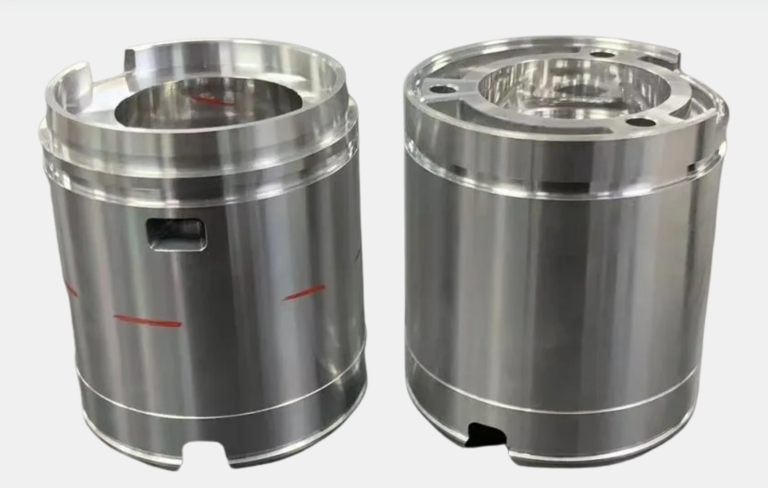
Many industries rely on flat-field correction to improve image quality and inspection accuracy. In manufacturing, line scan imaging systems check products for defects as they move along conveyor belts. These systems need correction to handle uneven lighting and dust on lenses. Electronics factories use line scan imaging to inspect circuit boards. Correction helps them find tiny faults that could cause device failure. The pharmaceutical industry uses line scan imaging for tablet inspection. Correction ensures that every tablet meets strict quality standards. High spatial resolution and high sensitivity are important in these fields. Correction allows systems to detect small defects and changes in product appearance.
A table below shows common applications:
| Industry | Application | Benefit of Correction |
|---|---|---|
| Manufacturing | Line scan imaging for parts | Uniform images, fewer errors |
| Electronics | PCB inspection | Detects fine defects |
| Pharmaceuticals | Tablet inspection | Consistent quality control |
Implementation Tips
Successful integration of flat-field correction into a machine vision workflow requires careful planning. The imaging setup must capture flat field images under uniform illumination. Sensor characteristics, such as pixel sensitivity and dark current, affect the correction process. Software must use correction algorithms that address pixel-to-pixel variations and illumination artifacts. Background estimation techniques help achieve uniform image intensity and reduce artifacts from optics and lighting.
Best practices for correction include several steps:
- Use a uniform light source to capture white reference images.
- Subtract dark-current images to remove electronic noise.
- Collect images at different exposure times and fit a linear curve per pixel for accurate correction.
- Always verify that white reference images match current optical conditions.
- Avoid using outdated reference images, as they may not reflect changes in the system.
- Understand that simple division by a blank field image does not always remove artifacts like dust or brightness changes.
Tip: Some software only allows one white reference image for all wavelengths. This may not work well if the system uses different light sources or chemical dyes.
Line scan imaging systems benefit from these correction steps. They deliver clear images for fast, automated inspection. When teams follow these tips, they improve workflow efficiency and reduce manual adjustments. Correction ensures that machine vision systems maintain high sensitivity and reliable performance in demanding environments.
A flat field correction machine vision system quickly removes blurry spots and uneven lighting from every image. This correction improves image quality by compensating for sensor imperfections and lighting issues. Teams see fewer artifacts and need less manual adjustment, which increases workflow efficiency. Experts recommend understanding the imaging setup and using proper calibration for the best results. > For organizations seeking reliable correction, consulting with machine vision experts can speed up deployment and ensure lasting success.
FAQ
What is the main purpose of flat-field correction in machine vision?
Flat-field correction removes uneven brightness and sensor noise from images. This process helps the system produce clear and uniform pictures. Teams use it to improve defect detection and measurement accuracy.
How often should a machine vision system perform calibration?
Teams should calibrate the system whenever they change the camera, lens, or lighting. Regular calibration also helps maintain accuracy if the environment changes, such as temperature shifts.
Can flat-field correction fix all blurry images?
Flat-field correction improves uneven lighting and sensor issues. It cannot fix motion blur or focus problems. Teams must address camera shake or incorrect focus separately.
Does flat-field correction slow down image processing?
Most modern systems apply flat-field correction in real time. Hardware like FPGAs or fast processors ensures that correction does not slow down inspections.
Which industries benefit most from flat-field correction?
| Industry | Benefit |
|---|---|
| Manufacturing | Fewer inspection errors |
| Electronics | Better defect detection |
| Pharmaceuticals | Consistent product quality |
Many industries use flat-field correction to improve quality and speed up inspections.
See Also
Ensuring Precise Alignment With Machine Vision Technology In 2025
Understanding Flaw Identification Using Machine Vision Solutions
Capabilities Of Machine Vision Systems In Detecting Defects
Does Filtering Improve Accuracy In Machine Vision Systems
Introductory Guide To Calibrating Vision Systems With Software